Shielding for cathodic arc metal ion sources

A shielding device, ion source technology, applied in ion implantation plating, metal material coating process, coating and other directions, can solve the problems of reduced deposition uniformity, incomplete solution, central ion beam current intensity, etc.

Active Publication Date: 2011-12-28
北京镨玛瑞驰科技有限公司
View PDF9 Cites 6 Cited by
  • Summary
  • Abstract
  • Description
  • Claims
  • Application Information

AI Technical Summary

Problems solved by technology

When the magnetic field decreases, the swing width of the arc spot increases, and the utilization rate of the target material increases, but it is possible that the arc spot enters the opposite runway at a certain position in the middle, turns back at a certain position of the circular runway, and does not completely close the runway The discharge causes the ion beam current to be strong in the middle and weak at both ends, reducing the uniformity of deposition
For this reason, there are patents using electromagnetic scanning magnetic field technology to improve the above phenomenon, but it has not been completely resolved.

Method used


Image

  • Shielding for cathodic arc metal ion sources
  • Shielding for cathodic arc metal ion sources
  • Shielding for cathodic arc metal ion sources

Examples


Embodiment Construction

[0036] Preferred embodiments of the present invention will be described in detail below with reference to the accompanying drawings, which are only exemplary and not drawn to scale, and the same or similar elements in the drawings are represented by the same reference numerals. The preferred embodiments shown in the drawings are only for better description of the present invention, and are not intended to limit the present invention. The scope of the present invention is defined by the scope of the appended claims.

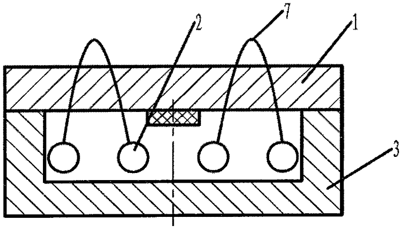
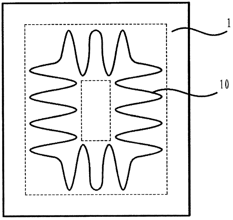
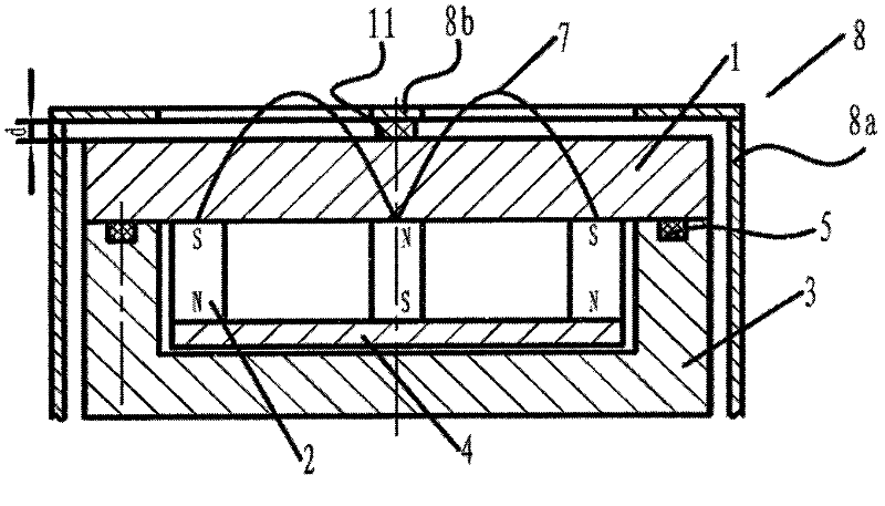
[0037] image 3 A shielding device for a cathodic arc ion source manufactured in accordance with a first embodiment of the present invention is shown, Figure 4It is a top view of the shielding device for the cathode arc ion source of this embodiment. Wherein the cathode arc ion source includes a target 1, a magnetic field assembly 2 located below the target 1, and an ion source body 3 that is hermetically connected to the target 1 through a seal 5 and encloses t...


PUM

PropertyMeasurementUnit
diameteraaaaaaaaaa
diameteraaaaaaaaaa
diameteraaaaaaaaaa

Abstract

The invention provides a shielding device for a cathode arc metal ion source. The cathode arc metal ion source comprises a target material, a magnetic field assembly located below the target material and producing a magnetic field above the target material, and an ion source hermetically connected with the target material to enclose the magnetic field assembly; the shielding device comprises marginal shielding pieces arranged around but spaced from the margin of the target material and a central shielding piece located above the center of the target material and positioned at the center relative to the marginal shielding pieces. Application of the central shielding piece and the marginal shielding pieces provided in the invention and an arc closed magnetic field constructed on the surface of a cathode target material by using a magnetic circuit makes cathode spots only do unilateral zigzag movement along a rectangular annular runway, and therefore, nonuniformity of deposition caused by random reciprocation of arc spots at halfway can be avoided.

Description

technical field [0001] The invention relates to a cathode arc metal ion source, in particular to a shielding device for the cathode arc metal ion source. Background technique [0002] Using a vacuum cathode arc ion source is one of the main methods to generate metal ions. It can evaporate and ionize the cathode target in a vacuum environment to form plasma. The ionization rate of the evaporated target is greater than 80%. A negative voltage is applied to the cathode target of the cathode arc ion source, and the arc discharge on the surface of the target is excited by the arc striking device to form the cathode arc spot. The area is very small (<1mm 2 ) in the cathode arc spot, the locally applied power is very large (3KW), so that a local high temperature (>6000°C) is formed at the cathode arc spot, and the cathode material is evaporated and ionized into metal ions, which meet the surface of the workpiece in vacuum Condensation occurs to form a thin film or coating. ...

Claims


Application Information

Patent Timeline
Patent Type & Authority Applications(China)
IPC IPC(8): C23C14/35
Inventor 杨会生
Owner 北京镨玛瑞驰科技有限公司
Why Eureka
Try Eureka