A sound insulation structure with perforated panels

A perforated plate and sound insulation technology, which is applied in the direction of sound insulation and building components, can solve the problems of improving the sound insulation of sound insulation structures and sound insulation products, so as to improve the sound insulation performance, weaken the resonance effect, and achieve good insulation effect Effect

Inactive Publication Date: 2011-12-28
周国柱
View PDF5 Cites 20 Cited by
  • Summary
  • Abstract
  • Description
  • Claims
  • Application Information

AI Technical Summary

Problems solved by technology

Due to the coincidence effect and resonance effect when the multilayer board is combined, the existence of these two effects limits the improvement of the sound insulation of commonly used sound insulation structures; especially limits the improvement of the sound insulation of some sound insulation products, such as sound insulation windows
Therefore, there are many deficiencies and needs to be improved in the existing sound insulation structure.

Method used


Image

  • A sound insulation structure with perforated panels
  • A sound insulation structure with perforated panels
  • A sound insulation structure with perforated panels

Examples


Embodiment 1

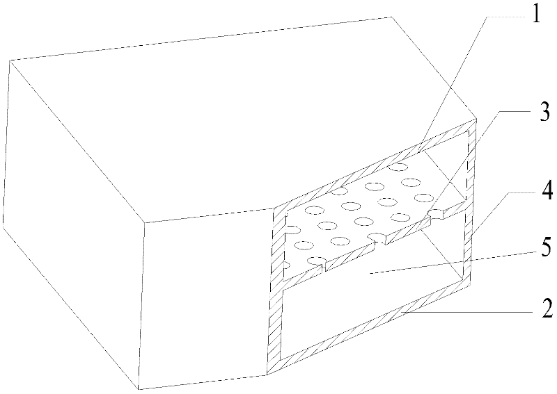
[0025] refer to figure 1 . Both the upper panel 1 and the lower panel 2 are glass plates (the glass plates include various glass plates such as quartz glass and organic glass). The thicknesses of the upper panel 1 and the lower panel 2 are respectively selected according to actual needs, such as 3 mm, 5 mm, 8 mm and so on. The perforated plate 3 is also a glass plate, and its thickness is a certain applicable value, such as 2 mm, 3 mm, 1.5 mm and so on. The hole diameter of the perforated plate 3 can be selected according to the thickness of the plate and the target anechoic frequency band, which is generally 0.2-3 mm. The hole diameter of the perforated plate 3 should be as small as possible under the premise of meeting the actual requirements. The perforation rate of the perforated plate 3 can be selected according to actual needs, and is generally 0.3%-6%. The perforation rate of the perforated plate 3 should be as small as possible under the premise of meeting the actu...

Embodiment 2

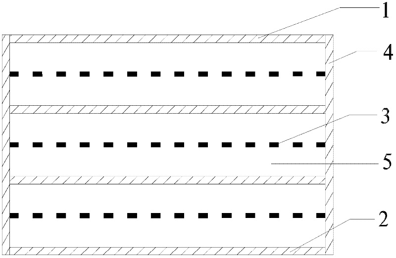
[0028] refer to figure 2 . The upper panel 1, the lower panel 2, the side panel 4, and the other two non-porous panels that play the role of the upper and lower panels in the figure are all steel plates, and the thickness of each panel can be a certain value, such as 1 mm, 2 mm, etc. The three perforated plates 3 in the figure can be thin steel plates with a thickness of 0.8 mm, a perforation diameter of 0.2-1 mm, and a perforation rate of 0.5%-5%. The distance between each perforated plate 3 and the adjacent upper and lower panels may be equal to an appropriate value, such as 5 cm, 8 cm or 20 cm. The cavity 5 formed by the three perforated plates 3 and their adjacent panels is filled with sound-absorbing materials, such as glass wool, polyurethane sponge and the like. The sound insulation structure produced by this scheme has a good sound insulation effect on medium and low frequency sounds, and has the characteristics of wide frequency band and high sound insulation.


PUM

PropertyMeasurementUnit
Perforation apertureaaaaaaaaaa
Thicknessaaaaaaaaaa
Perforation apertureaaaaaaaaaa

Abstract

The invention relates to a sound insulation structure with a perforated plate. The sound insulation structure with perforated panels is mainly composed of an upper panel, a lower panel, a perforated panel and side panels. The peripheries of the space clamped between the perforated plate, the upper panel and the lower panel are blocked by side panels to form two chambers. The two chambers respectively form a resonance sound-absorbing structure with the perforated plate. In the sound insulation structure with perforated panels of the present invention, the upper panel, the lower panel and the side panels are all made of blind panels without perforations. The distance between the perforated plate and the upper and lower panels can be equal or different.

Description

technical field [0001] The invention relates to a sound insulation structure, in particular to a sound insulation structure with a perforated plate. Background technique [0002] The use of sound insulation technology can effectively cut off the noise transmission path, which is a common means of noise control. At present, the commonly used sound insulation structures include single-layer homogeneous thin plate, single-layer composite sound insulation structure, double-layer sound insulation structure, various light sound insulation structures, single-layer heavy partition wall, double-layer heavy partition wall and multi-layer sound insulation structure. structure. Common sound insulation components, such as doors and windows, walls, floors, etc., can be attributed to the above sound insulation structures. [0003] Perforated panels are often used to cooperate with the back air layer to form a resonance and noise reduction structure. In order to widen the sound-absorbing...

Claims


Application Information

Patent Timeline
IPC IPC(8): E04B1/84
Inventor 周国柱
Owner 周国柱
Why Eureka
Try Eureka