An improved device for improving the efficiency of wind turbines or wind power generators

An improved technology for wind turbines, applied in the control of wind turbines, wind turbines, wind turbines consistent with the wind direction, etc., can solve the problems of low wind gathering efficiency, impracticality, and large span of disciplines, and achieve high efficiency Optimal, cost-optimized results

Inactive Publication Date: 2011-12-28
孟英志
View PDF6 Cites 1 Cited by
  • Summary
  • Abstract
  • Description
  • Claims
  • Application Information

AI Technical Summary

Problems solved by technology

"Its shortcoming is: in the middle of practical application, the wind gathering surface described in this embodiment has single directionality, does not rotate with the wind direction and rotates, therefore, its shortcoming is that if the wind is not from low When the direction of the surface is blown to the direction of the high surface, but when it is blown from the directions of two sides, then this invention has no effect, and it cannot achieve the purpose of improving the efficiency of the fan or wind power generator. In fact, it is almost useless Furthermore, even when the wind is blowing from the direction of the low surface to the direction of the high surface, since the wind gathering surface is completely located under the fan blade, although the wind passing through the fan blade below can be gathered, the wind gathering efficiency Low, only a small part of the wind can reach the effective part of the fan and blow to the tip of the fan blade, while a large part of the wind blows from the bottom of the fan and is wasted
[0004] When the inventor implemented the above-mentioned patent, he encountered many problems that had to be solved. In order to solve these problems, he also changed and designed many other schemes. In the process, he also filed patent applications for two schemes wherein, but All are not ideal, through thinking and experiment more than half a year, consulted many expert friends, especially introduced the concept of sensor and controller, because subject span is bigger, be difficult to understand, paid a lot of hard work; The present invention mainly Applied to large-scale wind turbines, in such a field, even a small technical change will cause a series of problems, such as the impact on the entire wind farm, the impact on the supporting generator, the impact on the load, Therefore, what seems to be a small improvement, in actual work, has paid a lot of creative labor.

Method used


Image

  • An improved device for improving the efficiency of wind turbines or wind power generators
  • An improved device for improving the efficiency of wind turbines or wind power generators
  • An improved device for improving the efficiency of wind turbines or wind power generators

Examples


Embodiment 1

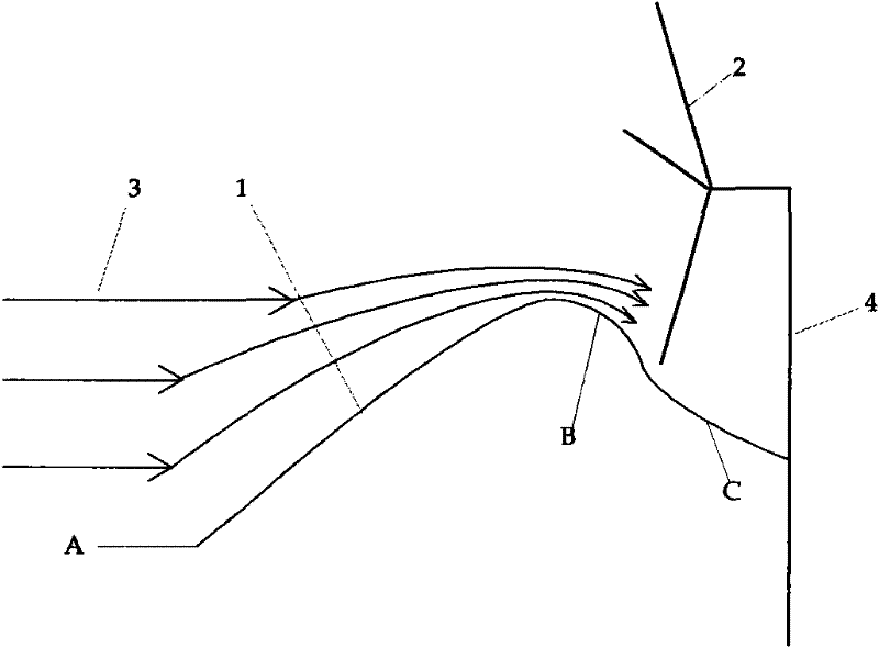
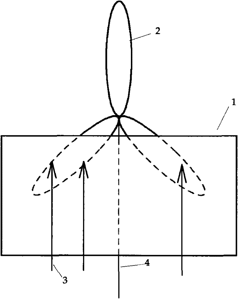
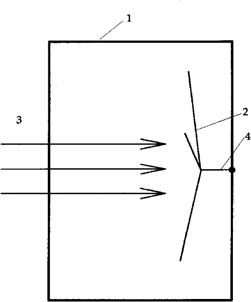
[0072] Such as figure 1 , figure 2 , image 3 , Figure 4 as shown, figure 1 It is a schematic diagram of the front view of a structural principle of the present invention, figure 2 It is a schematic diagram of the left view of the structural principle of the present invention, image 3 It is a top view schematic diagram of the structure principle of the present invention, Figure 4 It is an overall schematic diagram of a structure principle of the present invention. When the wind blows from the A-B section of the wind-gathering surface 1, the wind gathers at the top, and when it reaches the B-C section, it begins to spread, so that the fan blades are in the initial stage of spreading. According to the knowledge of physics, the wind direction and wind force at this time are in the position of doing work. In the optimal stage, the wind from section A-B can be blown and collected at the position of the sweeping surface of the blade, thereby improving the efficiency of th...

Embodiment 2

[0074] Similarly, if Figure 5 , figure 2 , image 3 , Image 6 as shown, Figure 5 It is a schematic diagram of the front view of a structural principle of the present invention, figure 2 It is a schematic diagram of the left view of the structural principle of the present invention, image 3 It is a top view schematic diagram of the structure principle of the present invention, Image 6 It is an overall schematic diagram of a structure principle of the present invention.

Embodiment 3

[0076] Similarly, if Figure 7 , figure 2 , image 3 , Figure 8 as shown, Figure 7 It is a schematic diagram of the front view of a structural principle of the present invention, figure 2 It is a schematic diagram of the left view of the structural principle of the present invention, image 3 It is a top view schematic diagram of the structure principle of the present invention, Figure 8 It is an overall schematic diagram of a structure principle of the present invention.


PUM


Abstract

The invention discloses a new device for increasing air volume and improving fan efficiency. The invention belongs to the technical field of wind energy utilization. And make the described wind gathering surface stable one or more support frames; on the support frame there is also installed a wind-facing device, the wind-facing device is connected with a fan or a wind generator; the support frame is composed of Rail or support cylinder shaft support.

Description

1. Technical field [0001] The invention belongs to the technical field of wind energy utilization, and is especially applicable to the technical fields of wind power machinery and wind power generation. 2. Background technology [0002] With the rapid development of the world economy and fierce competition, new energy power generation technology, especially wind power generation technology, has attracted more and more attention from all countries in the world. At present, the installed capacity of wind power in the world has reached 4.9 million kilowatts, and it is still growing at an average annual rate of 60%, reflecting a new trend in the development of international electric power. my country has abundant wind energy resources, and foreign mature technologies can be used for reference. The conditions for large-scale development of wind power have been met and should be actively developed. However, at present, the high cost of wind power has hindered the further developm...

Claims


Application Information

Patent Timeline
Patent Type & Authority Applications(China)
IPC IPC(8): F03D9/00F03D1/00F03D1/04F03D7/04
CPCY02E10/72Y02E10/723
Inventor 孟英志
Owner 孟英志
Why Eureka
Try Eureka