Eureka AIR delivers breakthrough ideas for toughest innovation challenges, trusted by R&D personnel around the world.

High-power voltage wide-range continuously adjustable constant-stable emission device

A transmitting device and wide-ranging technology, applied in the direction of output power conversion device, DC power input conversion to DC power output, electrical components, etc., can solve the problem of limited voltage adjustment range of high-power transmitters, capacity and quality of single generator sets Excessively large, non-continuous adjustment and other problems, to achieve the effect of quality and capacity reduction

Inactive Publication Date: 2011-12-28
BEIJING UNIV OF TECH
View PDF3 Cites 20 Cited by
  • Summary
  • Abstract
  • Description
  • Claims
  • Application Information

AI Technical Summary

Problems solved by technology

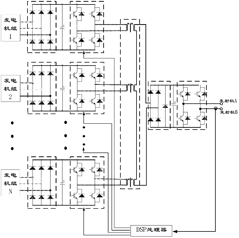
[0004] The purpose of the present invention is to overcome the disadvantages of the limited voltage adjustment range of the high-power transmitter, the non-continuous adjustment, and the large capacity and quality of the single generator set.

Method used

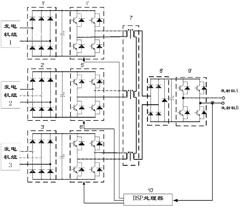

Image

  • High-power voltage wide-range continuously adjustable constant-stable emission device
  • High-power voltage wide-range continuously adjustable constant-stable emission device
  • High-power voltage wide-range continuously adjustable constant-stable emission device

Examples


Embodiment approach

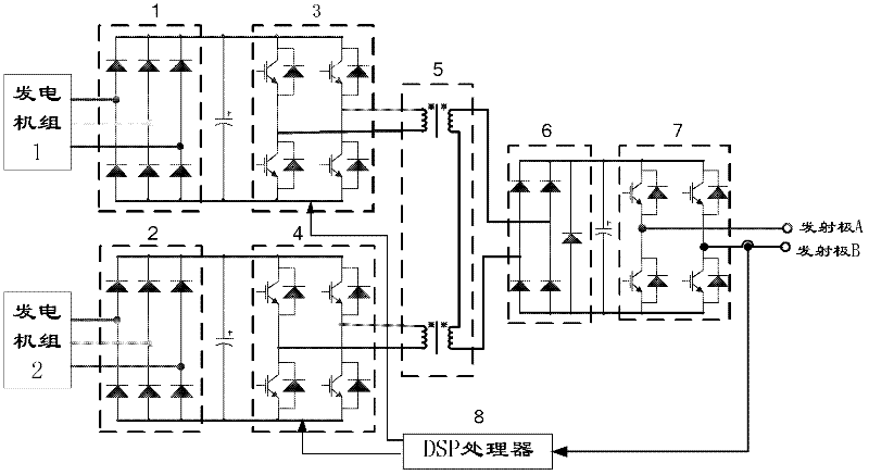
[0020] Take N=2 as an example for illustration.

[0021] Such as figure 2 As shown, the specific implementation of the hardware circuit of the present invention is as follows:

[0022] Two three-phase generator sets provide three-phase AC voltage input to two three-phase rectifiers 1 and 2. The three-phase rectifier rectifies the three-phase AC voltage and then inputs it to the filter capacitor. The filter capacitor outputs a DC voltage, and the filter capacitor outputs a DC voltage. Input to two high-frequency inverters 3 and 4, the high-frequency inverter outputs high-frequency AC voltage, and the output of the high-frequency inverter is input to the high-frequency transformer 5, and the boosted high-frequency voltage output by the high-frequency transformer The voltage is then input to the single-phase rectifier bridge, and the output of the single-phase rectifier bridge is input to the fully-controlled H-bridge after passing through the filter, and the fully-controlled H...

specific Embodiment approach

[0025] Such as Figure 9 As shown, the specific implementation of the control platform of the present invention is as follows:

[0026] The high-power constant-stable transmitter can emit constant voltage or constant current with changing frequency. At different frequencies, due to the skin effect, capacitance, and inductance, the equivalent impedance between emitters changes with frequency. For example, in geological exploration, the impedance of the ground between the transmitting electrodes varies as much as 100Ω in different frequency bands. Therefore, if you want to emit a constant current, you must make the emission voltage increase with the increase of impedance. In order to achieve constant current emission, it is necessary to control the duty cycle or phase difference of the output voltages on the two high-frequency inverters so that the output voltage of the high-frequency transformer meets the emission requirements.

[0027] According to the above description, th...


PUM


Abstract

The invention provides a large-power steady transmitting device with a continuously adjustable voltage width range. The device is characterized in that current is respectively input into a three-phase rectifier, a high-frequency inverter, a high-frequency transformer and the like by multiple generator sets, the output end of the high-frequency transformer performs power synthesis and then outputs voltage commutation, and a constant-current output device capable of adjusting output voltages within a large range can be realized through a control inverter circuit. According to the invention, the capacity of a single generator can be effectively reduced, the output voltage can be adjusted within a wide range, the control strategy is simple, and high-current, high-precision and steady load can be realized.

Description

technical field [0001] The invention relates to a set of power electronic devices for constant voltage or constant current emission, such as geological exploration, marine resource detection and other fields. Background technique [0002] There are not many R&D institutions at home and abroad for constant stability transmitters, and its main feature is that it can emit constant voltage or current with changing frequency. [0003] When the constant-stable transmitter transmits a constant voltage or current, since the transmission frequency can be continuously changed, the impedance between the emitters also changes with the frequency. And when the transmission frequency changes greatly, such as DC-1KHz, the impedance between the emitters varies as much as 100Ω. The change in impedance between the two poles is due to the combined effect of the skin effect, capacitance, and inductance. When the frequency between the emitters changes greatly, the impedance between the two pole...

Claims


Application Information

Patent Timeline
IPC IPC(8): H02M3/335
Inventor 张一鸣胡科堂陈东升高俊侠刘燕楠
Owner BEIJING UNIV OF TECH
Why Eureka
Eureka Blog
Learn More