Wind power or hydraulic power generation device

A technology of wind power and generator, which is applied in the direction of hydropower generation, wind power engine, wind power motor combination, etc., can solve the problems of high energy conversion efficiency, loud noise, unfriendly birds, etc., and achieve high utilization rate, easy operation, and design ideas concise effect

Inactive Publication Date: 2012-01-04
雷立旭
View PDF7 Cites 12 Cited by
  • Summary
  • Abstract
  • Description
  • Claims
  • Application Information

AI Technical Summary

Problems solved by technology

Its advantage lies in its high energy conversion efficiency, but its disadvantages are loud noise and unfriendly to birds; the vertical axis wind turbine is just the opposite, so it is suitable for densely populated places in

Method used


Image

  • Wind power or hydraulic power generation device
  • Wind power or hydraulic power generation device
  • Wind power or hydraulic power generation device

Examples


Embodiment 1

[0039] Example 1: Hydroelectric generator used on the beach

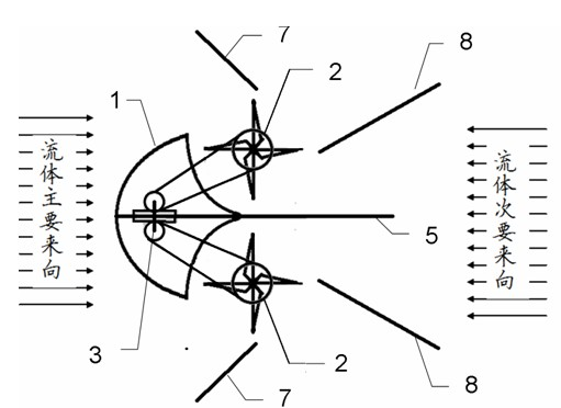
[0040] When the device is placed on the beach, the direction of water flow is two-way when the tide rises and falls, such as figure 2 The device shown is fixed on a base with its head facing the direction of the sea. In this way, when the fluid flows against the head or tail of the power generating device, both runners will rotate in the same direction and then drive the generator rotor to generate electricity.

[0041]

Embodiment 2

[0042] Example 2: Hydroelectric generator used in the river

[0043] When the device is used at the edge of a river, because the direction of the water flow is fixed, the device is fixed on the base and the rear shield is removed. Because the water velocity on the side near the river bank may be very small, the size of the two runners can be different to obtain a considerable thrust, or the runner near the bank can be removed, or even the half near the river bank and the generator can be directly connected to The runners are connected to obtain a lower cost.

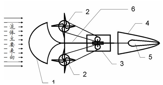
[0044] When used in the middle of the river, the velocity field of the water flow is evenly distributed, so it can be removed figure 2 The front and rear baffles in the middle leave only the fairing, the diversion and protection cover behind the runner (not shown in the figure for clarity), and the tail deflector, which can be made to float on the water. Fish-shaped device (such as figure 1 Shown). The device will be hel...

Embodiment 3

[0046] Example 3: High-altitude wind turbine

[0047] Such as figure 1 The wind power generation device shown has an aerodynamic shape to make it float high in the sky. The blades of the wind wheel can be specially designed (such as with Figure 5 c), and properly change the inclination angle of the tail horizontal deflector, so that the device can automatically generate lift in the wind, so that it can float in the air with bootstrapping. The generated electricity can be led to the ground (storage) appliance through the traction cable of the device.

[0048]


PUM


Abstract

The invention discloses a wind power or hydraulic power generation device. In the device, one end of a bracket (6) is connected with a fairing (1), and the other end of the bracket (6) is connected with a horizontal tail (4) and a vertical tail (5) connected with the horizontal tail (4) and vertical to the horizontal tail (4); and a rotating wheel (2) and a generator (3) driven by the rotating wheel (2) are arranged on the bracket (6) between the fairing (1) and the horizontal tail (4). The device can be flexibly reformed according to application occasions, and a third rotating wheel and a fourth rotating wheel can be arranged to adapt to different power generation occasions and improve the energy conversion efficiency. The invention belongs to the technical field of renewable energy source (wind energy, running water energy and tidal energy) power generation.

Description

technical field [0001] The invention relates to a device that can be used for wind or hydroelectric power generation. It belongs to the field of renewable energy (wind energy, flowing water energy, tidal energy) power generation technology. Background technique [0002] In recent years, depletable primary energy has presented its unsustainable problem time and time again. The high price of oil has caused the threat of war to appear again and again in oil-producing areas or during oil transportation; the unusability of coal has repeatedly used mine disasters and air pollution to show its power to people. This has led people to once again turn their attention to clean and sustainable energy sources - solar energy, tidal energy, and hope for effective energy conversion devices and conversion materials. [0003] Wind energy, elevated reservoirs, and continuous running water all come from solar energy. Because the inhomogeneity of the solar energy radiation effect causes the a...

Claims


Application Information

Patent Timeline
IPC IPC(8): F03D9/00F03D3/02F03D3/04F03B13/00F03B13/26F03B3/00F03B3/18F03D9/25
CPCY02E10/74Y02E10/223Y02E10/28Y02E10/20Y02E10/30
Inventor 雷立旭王玉玲
Owner 雷立旭
Why Eureka
Try Eureka