Novel MEMS (micro electro mechanical system) centrifugal-type gyroscope

A centrifugal and gyro technology, which is applied in the field of inertial measurement, can solve the problems of high noise of MEMS vibrating gyro, high cost of MEMS rotor gyro, and orthogonal coupling error, etc., so as to improve the stability of zero bias, reduce energy consumption, and improve The effect of precision

Inactive Publication Date: 2013-04-17
NORTHWESTERN POLYTECHNICAL UNIV
View PDF5 Cites 3 Cited by
  • Summary
  • Abstract
  • Description
  • Claims
  • Application Information

AI Technical Summary

Problems solved by technology

[0007] The purpose of the present invention is: in order to overcome the existing MEMS vibrating gyroscope high noise, poor bias stability and the existence of orthogonal coupling error, and MEMS rotor gyroscope high cost, the shortcomings of complex control, the present invention discloses a new type of MEMS centrifugal gyroscope Gyro

Method used


Image

  • Novel MEMS (micro electro mechanical system) centrifugal-type gyroscope
  • Novel MEMS (micro electro mechanical system) centrifugal-type gyroscope
  • Novel MEMS (micro electro mechanical system) centrifugal-type gyroscope

Examples


Embodiment 1

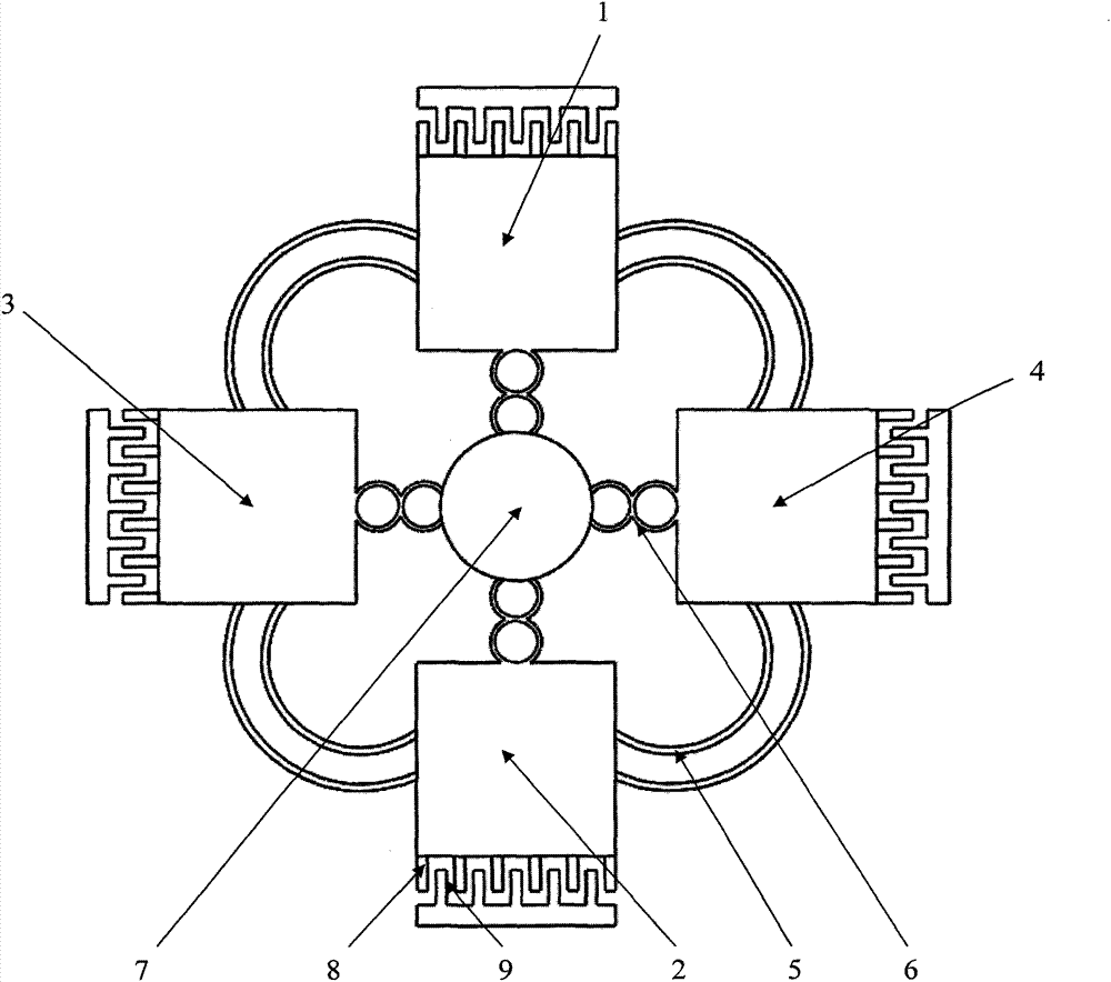
[0018] refer to figure 1 , a MEMS centrifugal gyro, comprising a first mass 1, a second mass 2, a third mass 3, a fourth mass 4, a decoupling beam 5, an elastic beam 6, a central anchor point 7, and movable comb teeth 8 and fixed comb teeth 9; the first mass block 1, the second mass block 2, the third mass block 3, and the fourth mass block 4 are evenly distributed around the center anchor point 7 in a ring, the first mass block 1, the second mass block The mass block 2, the third mass block 3, the fourth mass block 4 and the central anchor point 7 are all connected by elastic beams 6; adjacent mass blocks are connected by two parallel arc-shaped decoupling beams 7; the first A set of movable comb teeth 8 are respectively arranged on the mass 1 , the second mass 2 , the third mass 3 and the fourth mass 4 , and form a comb capacitance with the corresponding fixed combs 9 .

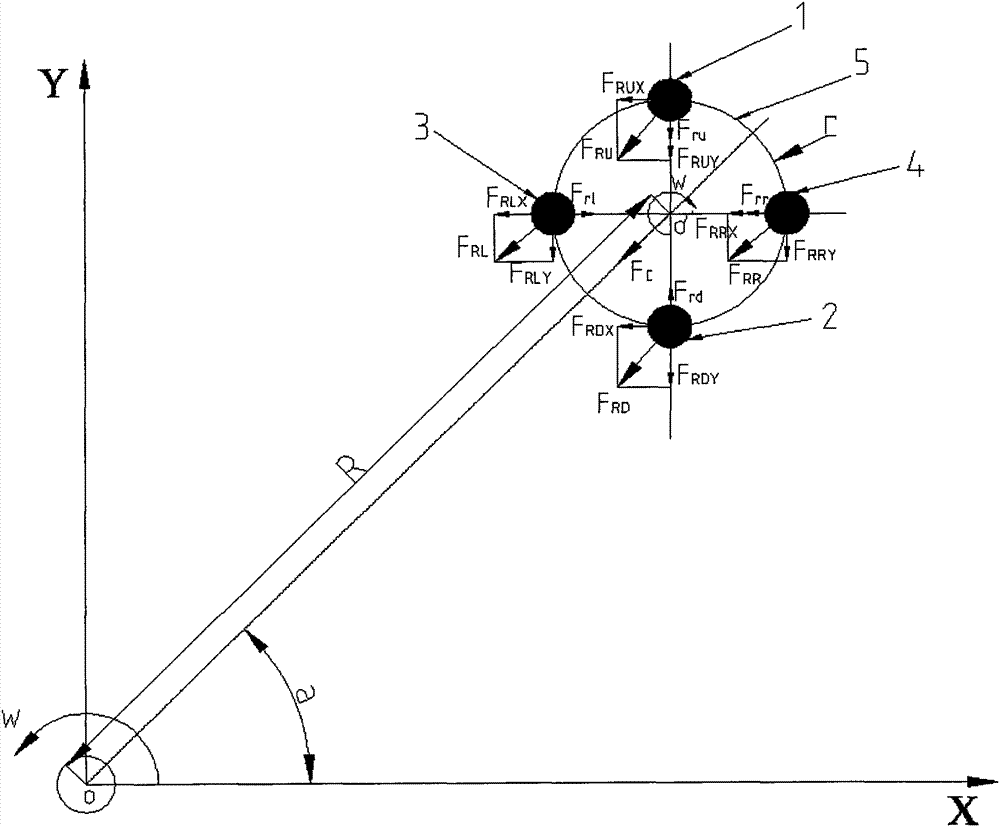
[0019] Theoretical analysis of MEMS centrifugal gyroscope in the present embodiment is as follows ima...

Embodiment 2

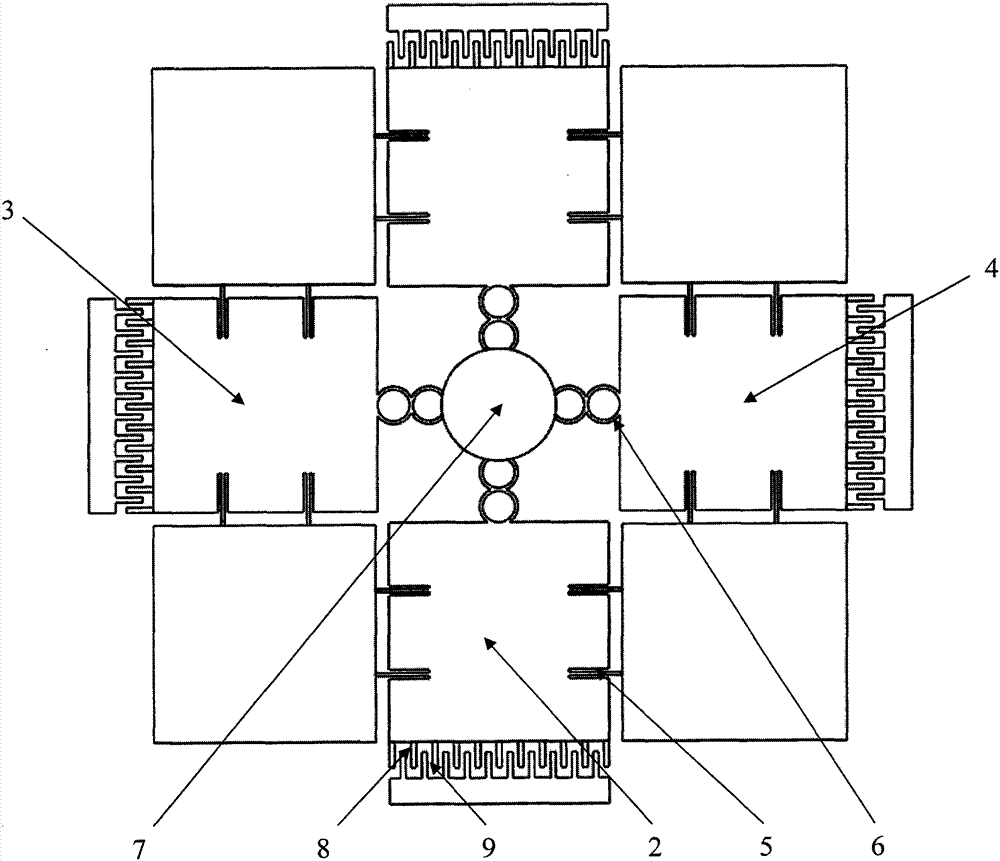
[0025] refer to figure 2 , the MEMS centrifugal gyro of the present embodiment includes a first mass 1, a second mass 2, a third mass 3, a fourth mass 4, a decoupling beam 5, an elastic beam 6, a central anchor point 7, a movable Comb teeth 8, fixed comb teeth 9 and diagonal anchor points 10; the first mass block 1, the second mass block 2, the third mass block 3, and the fourth mass block 4 are evenly distributed around the center anchor point 7 , the first mass 1, the second mass 2, the third mass 3, the fourth mass 4 and the central anchor point 7 are all connected by elastic beams 6; between two adjacent mass blocks is a diagonal anchor point 10, and each mass is supported and suspended on two adjacent diagonal anchor points 10 by the decoupling beam 5; the first mass 1, the second mass 2, the third mass 3 and the fourth mass A group of movable comb teeth 8 are respectively arranged on the 4, and form a comb tooth capacitor with corresponding fixed comb teeth 9. The dis...


PUM


Abstract

The invention discloses a novel MEMS (micro electro mechanical system) centrifugal-type gyroscope technology, belonging to the field of inertia measurement. Four mass blocks of a gyroscope are distributed annularly and uniformly at the periphery of a central anchor point 7, and each mass block and the central anchor point 7 are connected through an elastic beam 6; the adjacent mass blocks are connected through two parallel arc decoupling beams 7; and a group of movable comb teeth 8 are distributed on each mass block 4, and form comb tooth capacitance with corresponding fixed comb teeth 9. When the angularity speed is input in the environment, the MEMS centrifugal-type gyroscope is subjected to displacement because of centrifugal force, and the angularity speed which is input in the environment can be reckoned through the detection of the displacement. Compared with the other MEMS gyroscopes, the gyroscope is not required to be driven, the detection of the angularity speed can be realized by utilizing the inertial motion of the gyroscope, thus the energy consumption is reduced; driving does not exist, the Brown noise can be reduced greatly, and the zero deflection stability is improved greatly; and simultaneously the cross coupling error of the MEMS oscillating-type gyroscope can be eliminated, and the precision is improved.

Description

[0001] Field [0002] The invention proposes a novel MEMS centrifugal gyroscope technology, which belongs to the field of inertial measurement. Background technique [0003] With the development of micro-electromechanical system MEMS technology, as a micro-mechanical gyroscope for measuring the angular velocity or angle of an object relative to the inertial space, it has the advantages of small size, light weight, low cost, low power consumption, and high reliability. Inertial navigation, robot control and other military and civilian fields have broad application prospects, especially for weapons and equipment such as micro-satellites and micro-aircraft, which have put forward the requirements of small size and high precision for micro-gyroscopes. Low-cost, high-precision and multi-input axis micromachined gyroscopes have become the main research direction of microgyroscopes. [0004] Existing MEMS gyroscopes are mainly divided into MEMS vibrating gyroscopes and MEMS rotor gy...

Claims


Application Information

Patent Timeline
Patent Type & Authority Patents(China)
IPC IPC(8): G01C19/02G01C19/42B81B3/00
Inventor 苑伟政谢中建李小卿谢建兵常洪龙
Owner NORTHWESTERN POLYTECHNICAL UNIV
Why Eureka
Try Eureka