

Power thermocouple conversion element with long-range concentrated cooling mode
Patent Information
- Authority / Receiving Office
- CN · China
- Patent Type
- Applications(China)
- Current Assignee / Owner
- SOUTH CHINA UNIV OF TECH
- Publication Date
- 2012-01-04
- Estimated Expiration
- Not applicable · inactive patent
Smart Images
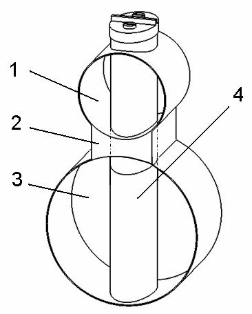
Figure 1 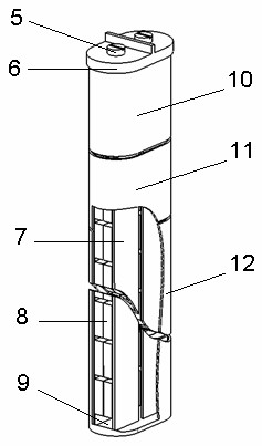
Figure 2 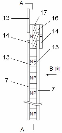
Figure 3
Abstract
Description
technical field
[0001] The invention relates to a thermoelectric direct conversion element, in particular to a long-distance centralized cooling power thermocouple conversion element. Background technique
[0002] The basis of thermoelectric conversion is Seebeck effect, Peltier effect and Thomson effect. When two conductors of different materials are connected into a closed loop, and the temperature of the joints (or junctions) at both ends of the loop is different, a current will be generated in the loop. This circuit is called thermoelectric circuit, the current is called thermal current, and the corresponding electromotive force is called thermal electromotive force or Seebeck electromotive force; among them, the node with high temperature is called working end or hot end, and the node with low temperature is called reference end or cold end. Industrial techniques are used to weld the joints into a common product called a thermocouple.
[0003] At present, dynamic the...