Atomic time signal receiving system and method

A signal receiving, atomic time technology, applied in transmission systems, electromagnetic receivers, digital transmission systems, etc., can solve the problems of limiting the use range of users and the small coverage area of ​​the atomic time signal optical fiber transmission system, so as to improve the utilization efficiency and expand the The effect of reception range

Active Publication Date: 2012-01-04
TSINGHUA UNIV
View PDF2 Cites 10 Cited by
  • Summary
  • Abstract
  • Description
  • Claims
  • Application Information

AI Technical Summary

Problems solved by technology

[0005] Compared with the method of using satellites to transmit time and frequency, although the above-mentioned atomic time signal optical fiber transmission system has very high transmission stability, only in the specific positions of the relay receiving device and the terminal receiving device can the atomic time signal of the transmitting end be reproduced. , it is difficult to reproduce high-quality atomic time signals at any point on the entire fiber link
As a result, the coverage area of ​​this atomic time signal optical fiber transmission system is relatively small, which limits the scope of use of users

Method used


Image

  • Atomic time signal receiving system and method
  • Atomic time signal receiving system and method
  • Atomic time signal receiving system and method

Examples


Embodiment Construction

[0028] In order to make the object, technical solution and advantages of the present invention clearer, the present invention will be further described in detail below in combination with specific embodiments and with reference to the accompanying drawings.

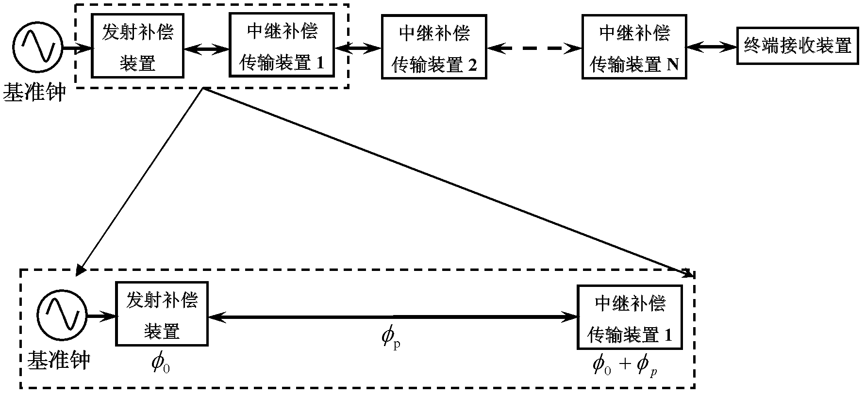
[0029] figure 1 A schematic diagram of the structure of an existing atomic time signal optical fiber transmission system is shown.

[0030] Refer below figure 1 The existing atomic time signal optical fiber transmission system is introduced.

[0031] Such as figure 1 As shown, the existing atomic time signal transmission system includes: a launch compensation device, which is used to modulate the atomic time signal to be transmitted onto an optical signal for transmission through an optical fiber, and compensate for the Phase noise; multiple relay compensation transmission devices are used to further compensate the phase noise introduced when the atomic time signal is transmitted in the optical fiber link. Wherein, th...


PUM


Abstract

The invention discloses an atomic time signal receiving system and method. The system comprises a microwave detection part and a microwave signal processing part, wherein the microwave detection part is used to couple an optical signal at an atomic time signal receiving position at any position in an optical fiber link and then demodulate a microwave signal on the optical signal; the microwave signal processing part is used to reproduce an atomic time signal of which the phase is locked on a reference clock on the basis of the demodulated microwave signal; and the microwave detection part can respectively couple parts of the optical signals transmitted along the opposite directions in the optical fiber link and then perform a demodulation process. According to the atomic time signal receiving system, atomic time signal of which the phase is locked on the reference clock can be reproduced at any position in the compensated signal transmission system of the optical fiber link, thus the application range of the atomic time signal fiber transmission system can be enlarged.

Description

technical field [0001] The invention relates to a system and method for receiving an atomic time signal. In particular, it relates to a system and method capable of receiving atomic time signals at any place in an ultra-long baseline atomic time signal optical fiber transmission system. Background technique [0002] At present, there are three main directions in the research and application of time-frequency systems. One is the preparation of the time frequency source, which is used to provide the time reference. The second is the transmission system of time and frequency. With a good reference source, it is necessary to accurately release the time and frequency. Therefore, the quality of the time-frequency transmission system directly determines the quality of the time-frequency signal received by the user end. This problem is especially important in ultra-long-distance time-frequency signal transmission. The third is the reception of time-frequency signals, such as GPS...

Claims


Application Information

Patent Timeline
Patent Type & Authority Applications(China)
IPC IPC(8): H04L7/00H04B10/12H04B10/25H04B10/60
Inventor 王力军王波高超苗菁
Owner TSINGHUA UNIV
Why Eureka
Try Eureka