
Condensation pipe and filtering module using same

A filtration module and condensation tube technology, applied in the direction of steam condensation, total evaporation, semi-permeable membrane separation, etc., can solve the problems of low specific surface area of ​​membrane, large fiber pressure difference, inconvenience, etc., to improve the permeation flux and increase the flux Effect

Inactive Publication Date: 2012-01-11
CHUNG YUAN CHRISTIAN UNIVERSITY
View PDF5 Cites 5 Cited by
  • Summary
  • Abstract
  • Description
  • Claims
  • Application Information

AI Technical Summary

Problems solved by technology

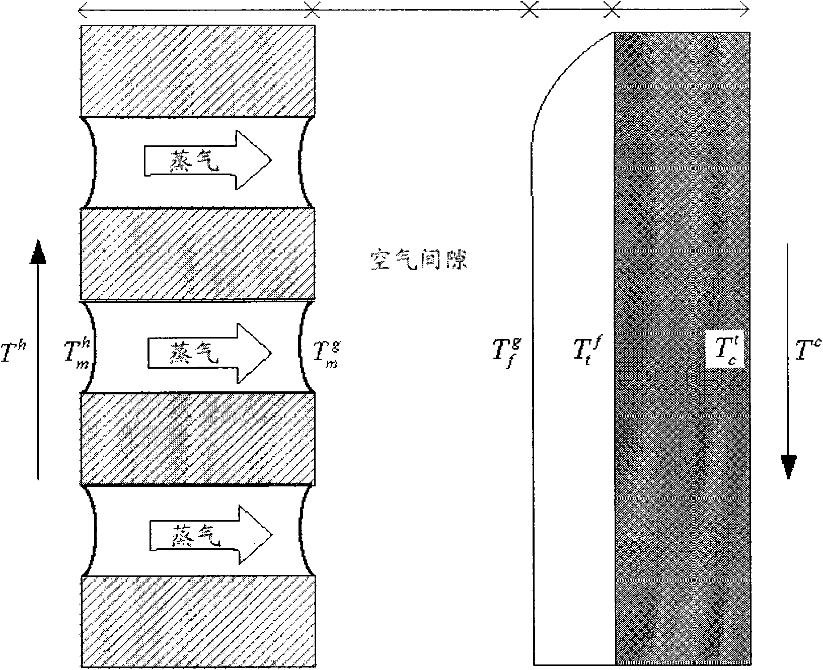
[0003] At present, although there are reports on the manufacture and design of various high-permeability membranes in the theoretical and experimental literature about air-gap thin-film distillation, there is no practical air-gap thin-film distillation (AGMD) module or system in industry so far. It is a non-isothermal process, so the design of thin film distillation not only needs to provide good flow conditions, low pressure difference and high packing density, but also needs to ensure good heat recovery function and thermal stability
Although in plate and frame module (Liu, G.L.; Zhu, C.; Cheng, C.S.; Leung, C.W., Theoretical and experimental studies on air gap membrane distillation. Heat Mass Transf.1998.34, 329) flat film Shows the highest permeate flux, but the lowest specific surface area for single-module membranes
On the other hand, although modules using hollow fibers (Cheng, L.H.; Wu, P.-C.; Chen, J. Numerical simulation and optimal design of AGMD-based hollow fibermodules for desalination. Ind. Eng. Chem. Res. 2009 , 48, 4948) can have the highest packing density, but the pressure drop along the fiber is the largest because of the diameter-to-length ratio of the fiber
[0004] It can be seen that the above-mentioned existing thin film distillation module or system obviously still has inconvenience and defects in structure and use, and needs to be further improved urgently.
In order to solve the above-mentioned problems, the relevant manufacturers have tried their best to find a solution, but no suitable design has been developed for a long time, and the general products do not have a suitable structure to solve the above-mentioned problems. This is obviously related. The problem that the industry is eager to solve

Method used


Image

  • Condensation pipe and filtering module using same
  • Condensation pipe and filtering module using same
  • Condensation pipe and filtering module using same

Examples


Embodiment Construction

[0058] In order to further explain the technical means and effects that the present invention takes to achieve the intended purpose of the invention, below in conjunction with the accompanying drawings and preferred embodiments, the specific implementation, structure, and Features and their functions are described in detail below.

[0059] Some embodiments of the present invention will be described in detail as follows. However, in addition to the following descriptions, the present invention can also be widely implemented in other embodiments, and the protection scope of the present invention is not limited by the embodiments, which shall prevail by the protection scope of the claims. Moreover, in order to provide a clearer description and an easier understanding of the present invention, various parts in the drawings have not been drawn according to their relative sizes, and some dimensions have been exaggerated compared with other relevant dimensions; irrelevant details hav...


PUM


Abstract

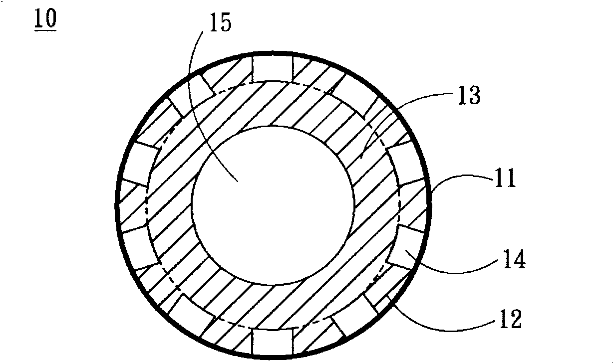
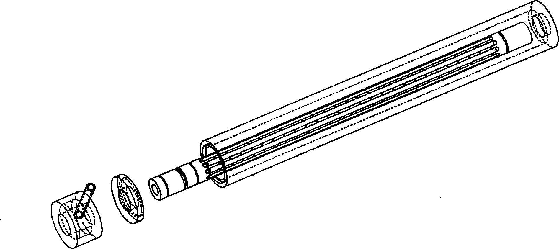
The invention relates to a condensation pipe and a filtering module using the same. The condensation pipe is a component for condensation of thin film distillation and comprises a hollow core body, a porous cladding layer and a condensation chamber, wherein the hollow core body is provided with a hollow compartment; the porous cladding layer has air permeability, but liquid cannot permeate the porous cladding layer; and the condensation chamber is formed by a space between the hollow core body and the porous cladding layer, and comprises an outlet communicated with the exterior and a plurality of fins which are radially arranged along the hollow core body and divide the condensation chamber into a plurality of condensation compartments.

Description

technical field [0001] The invention relates to a component for thin film distillation, in particular to a condensation tube which is applied to air gap membrane distillation (air-gap membrane distillation; AGMD) and can increase the flux of thin film distillation and further increase the distillation speed and the filter modules that use it. Background technique [0002] Thin-film distillation is a distillation process that separates a high-temperature liquid from a low-temperature liquid by a porous film that allows vapor but not liquid to pass through. Methods using thin film distillation can generally be classified into direct-contact membrane distillation (DCMD), air-gap membrane distillation (AGMD), and air-swept membrane distillation (sweeping-gas membrane distillation; SGMD). ) and vacuum membrane distillation (vacuum membrane distillation; VMD) four. Among them, air gap thin film distillation has the highest thermal efficiency, and has been applied to various sepa...

Claims


Application Information

Patent Timeline
IPC IPC(8): B01D61/36B01D65/00B01D5/00
CPCB01D61/368
Inventor 陈荣辉林昱宏
Owner CHUNG YUAN CHRISTIAN UNIVERSITY
Learn More