

Method for sealing edge of vacuum glass
A vacuum glass and edge sealing technology, which is applied in glass forming, glass reshaping, glass manufacturing equipment, etc., can solve the problems of vacuum glass edge unevenness, small flow resistance, sealing failure, etc., and achieve neat and beautiful solder edges, Good air permeability, airtightness improvement effect
- Summary
- Abstract
- Description
- Claims
- Application Information
AI Technical Summary
Problems solved by technology
Method used
Image

Examples
example 1
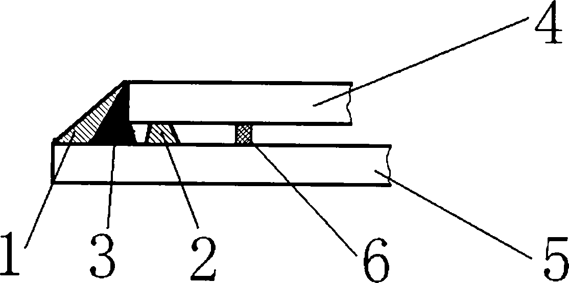
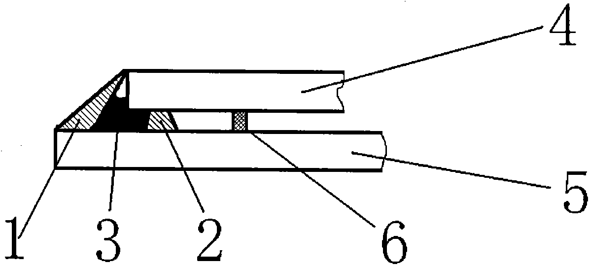
[0019] Example 1: if figure 1 As shown, the inner anti-seepage layer is placed first, and the inner anti-seepage layer is formed by mixing glass powder and glass solder with appropriate water in a ratio of 5:1. Next place the glass solder. Finally, the outer anti-seepage layer is applied, and the outer anti-seepage layer is formed by mixing aluminum oxide powder and water glass in a ratio of 2:1. Such as figure 2 As shown, the glass solder is condensed into a solid after being heated and melted, and the volume becomes smaller, and part of the molten glass solder penetrates into the gap between the upper and lower layers of glass. The outer barrier can be easily removed.
example 2
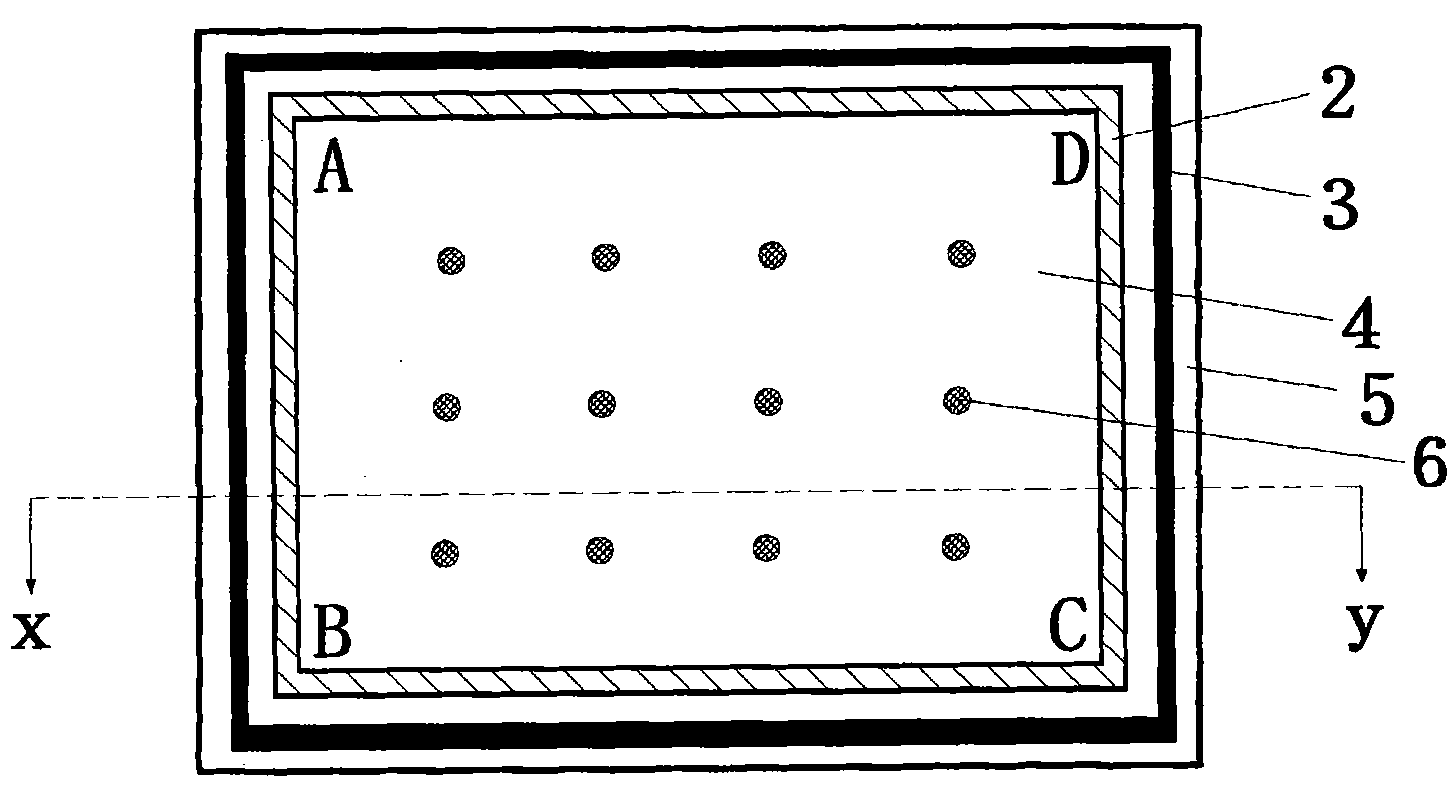
[0020] Example 2: such as Figure 5 As shown, first place the support body on the lower glass, then place the inner anti-seepage layer, the inner anti-seepage layer is composed of glass fiber, cover the upper layer of glass, then place the glass solder, and then place the outer anti-seepage layer around, the outer anti-seepage layer The infiltration layer is made by mixing glass powder and water glass in a ratio of 3:1. Put the vacuum glass original plate with anti-seepage layer and glass solder into the vacuum furnace to heat, wait until the bubbles in the glass solder melt are completely eliminated, stop heating, cool and then come out of the furnace. Before the bubbles in the glass solder melt are completely eliminated, the gas in the vacuum furnace must be pumped out continuously until the vacuum degree in the vacuum furnace reaches the set value (such as 0.001pa). If the upper glass plate has air extraction holes, the original vacuum glass plate only needs to be heated i...
PUM
 Abstract
Description
Claims
Application Information