
Driving component, cleaning device and ultraviolet sterilizing equipment

A technology for cleaning devices and driving components, which is applied in the direction of electric components, electromechanical devices, cleaning methods and appliances, etc. It can solve the problems of uneven movement speed, vibration, instability, etc., and achieve low cost, long service life and stable operation. Effect

Inactive Publication Date: 2012-01-11
SHENZHEN OCEAN POWER INDUSTRIAL CO LTD
View PDF5 Cites 11 Cited by
  • Summary
  • Abstract
  • Description
  • Claims
  • Application Information

AI Technical Summary

Problems solved by technology

The hydraulic drive method is unstable, and the movement speed will be uneven, resulting in serious vibration problems.

Method used


Image

  • Driving component, cleaning device and ultraviolet sterilizing equipment
  • Driving component, cleaning device and ultraviolet sterilizing equipment
  • Driving component, cleaning device and ultraviolet sterilizing equipment

Examples


Embodiment 1

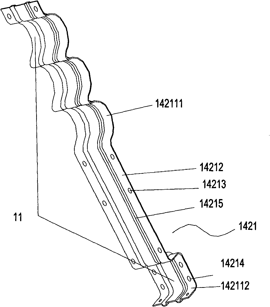
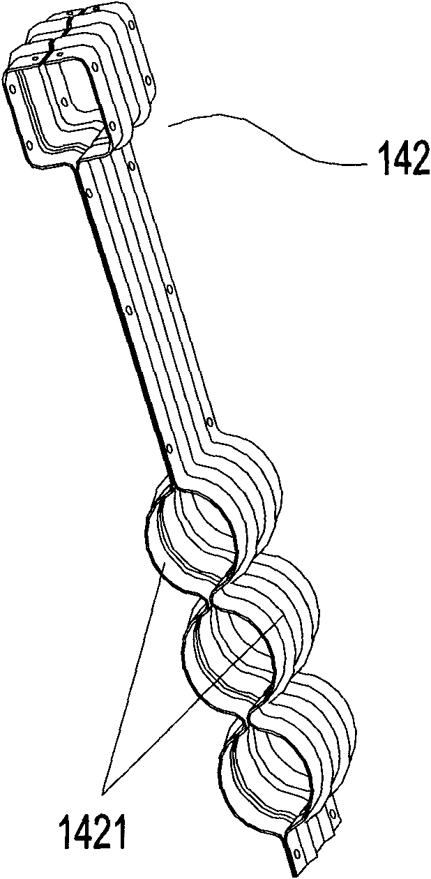
[0033] like Figure 9 As shown, an ultraviolet disinfection device 1 includes a housing 11, a fixed frame 12 supporting the housing 11, a plurality of ultraviolet lamps 13 arranged in parallel up and down on the fixed frame 12, and also includes a housing mounted on the fixed frame 12. The cleaning device 14, such as Figure 7 As shown, the cleaning device 14 includes a wiper 141 for wiping the ultraviolet lamp 13 , a clamping member 142 and a driving assembly 143 .

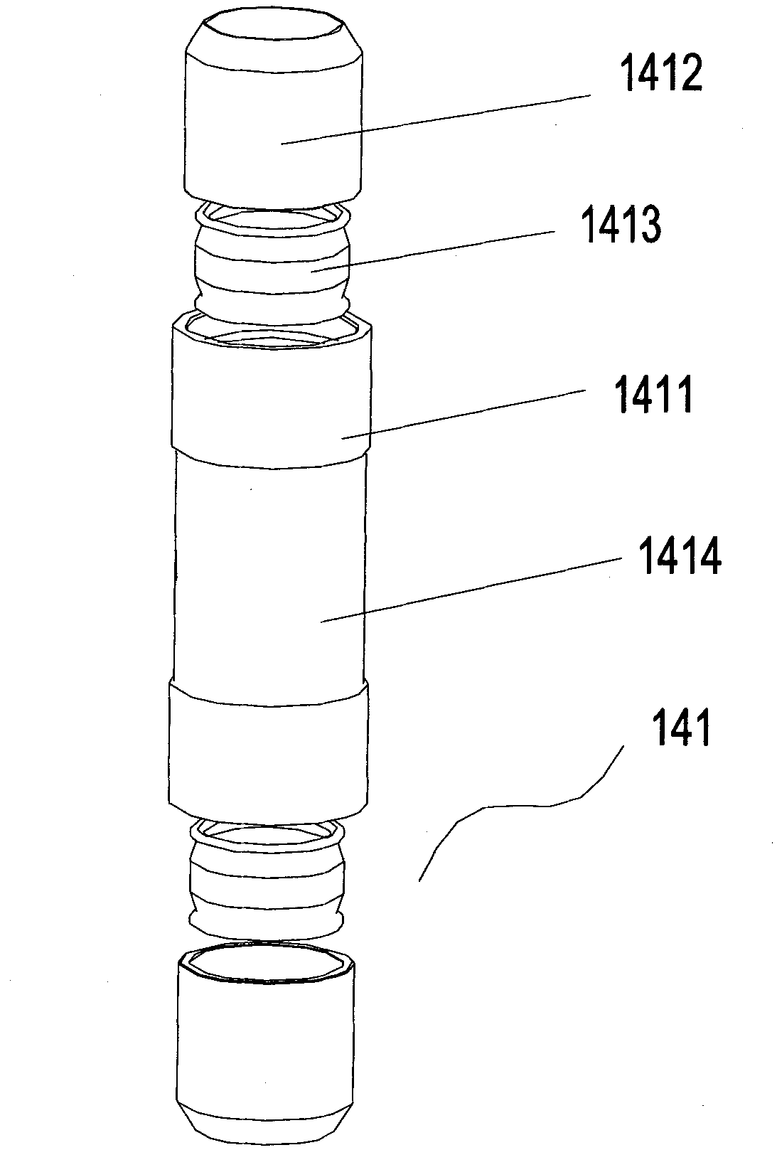
[0034] like image 3 As shown, the wiper 141 includes a wiper main sleeve 1411, two wiper secondary sleeves 1412 respectively installed at both ends of the wiper main sleeve 1411, the wiper main sleeve 1411 and two wipers A wiper inner annular groove (not shown in the figure) is divided between the secondary sleeve pipes 1412, and a wiper apron 1413 for wiping the ultraviolet lamp 13 is arranged in the wiper inner annular groove, and the wiper apron 1413 1413 is sleeved on the ultraviolet lamp tube 13, and the...

Embodiment 2

[0046] On the basis of above-mentioned embodiment 1, combine again Figure 8 and 10 As shown, the cleaning device 14 of the ultraviolet disinfection equipment 1 also includes a sensor 144 that establishes a signal transmission link with the controller. The sensor 144 is set outside the ultraviolet lamp 13. The sensor 144 includes a The wiping unit 1441 and the sensing unit (not shown) for sensing light intensity, the wiping unit 1441 includes a sensor main sleeve 14411, two sensor secondary sleeves 14412 installed at both ends of the sensor main sleeve 14411 A sensor inner annular groove 14413 is provided between the sensor main sleeve 14411 and the two sensor auxiliary sleeves 14412, and a sensor rubber ring (not shown in the figure) for wiping the ultraviolet lamp is arranged in the sensor inner annular groove 14413 ), the sensing unit is arranged on the inner wall of the sensor main sleeve 14411, and the middle part of the sensor main sleeve 14411 is clamped in the arches ...


PUM


Abstract

The invention relates to a driving component, a cleaning device with the driving component and an ultraviolet sterilizing equipment with the cleaning device, wherein the driving component comprises a motor, a controller, touch switches, a rotating screw rod and a transmission nut, wherein the controller controls the operation of the motor; the touch switch is connected with the controller; the rotating screw rod is driven by the motor; the transmission nut is sheathed outside a transmission screw rod; and the touch switches are close to the two ends of the rotating screw rod. The cleaning device comprises a wiper for wiping a lamp tube and a clamping piece, and is characterized by also comprising the driving component; and the wiper and the transmission nut are respectively and fixedly clamped on the clamping piece. In the driving component provided by the invention, the structure is simple, the installation is convenient, the cost is low, simultaneously the operation is stable, the service life is long and frequent maintenance is not needed.

Description

【Technical field】 [0001] The invention relates to a driving assembly, a cleaning device with the driving assembly and an ultraviolet disinfection device with the cleaning device. 【Background technique】 [0002] The ultraviolet lamp casing of the ultraviolet disinfection equipment is soaked in sewage for a long time, and it is easy to form dirt on the surface of the ultraviolet lamp casing. Therefore, it is necessary to use an automatic cleaning device to regularly clean the ultraviolet lamp casing. The automatic cleaning device generally includes The outer cylindrical wiper, the clamping part used to clamp the wiper and drive the wiper to wipe back and forth on the surface of the ultraviolet lamp sleeve, and the driving assembly used to drive the clamping part to reciprocate back and forth. Most of the existing driving components use hydraulic pressure or air pressure to push the clamping member to move, thereby driving the wiper to move. There is instability in the hydraul...

Claims


Application Information

Patent Timeline
Patent Type & Authority Applications(China)
IPC IPC(8): H02K7/10B08B1/00A61L2/10
Inventor 王松如何唯平
Owner SHENZHEN OCEAN POWER INDUSTRIAL CO LTD
Learn More