
Wireless base station clock synchronization method and system thereof, base band frame and exchange frame

A clock synchronization and wireless base station technology, which is applied to baseband system components, synchronization devices, synchronization devices, etc., to save costs and avoid engineering installation difficulties

Active Publication Date: 2012-01-11
ZTE CORP
View PDF2 Cites 5 Cited by
  • Summary
  • Abstract
  • Description
  • Claims
  • Application Information

AI Technical Summary

Problems solved by technology

Therefore, for this kind of networking situation, the first timing scheme mentioned above can be adopted, but at the same time, it also needs to bear the unfavorable factors such as cost and engineering brought by the first timing scheme
[0005] In the prior art, there are mainly two methods for synchronization: one is to use the GPS system to serve time to the base station, so that all BBUs can be synchronized to a reference clock; the other is to add an additional clock cascading cable to connect the time phase of one BBU through the line The other BBUs are synchronized with the transmitted phase, so as to achieve phase synchronization of all BBUs in the cluster. Both methods require additional equipment or cables

Method used


Image

  • Wireless base station clock synchronization method and system thereof, base band frame and exchange frame
  • Wireless base station clock synchronization method and system thereof, base band frame and exchange frame
  • Wireless base station clock synchronization method and system thereof, base band frame and exchange frame

Examples


Embodiment Construction

[0051] In order to make the purpose, technical solution and advantages of the present invention more clear, the embodiments of the present invention will be described in detail below in conjunction with the accompanying drawings. It should be noted that, in the case of no conflict, the embodiments in the present application and the features in the embodiments can be combined arbitrarily with each other.

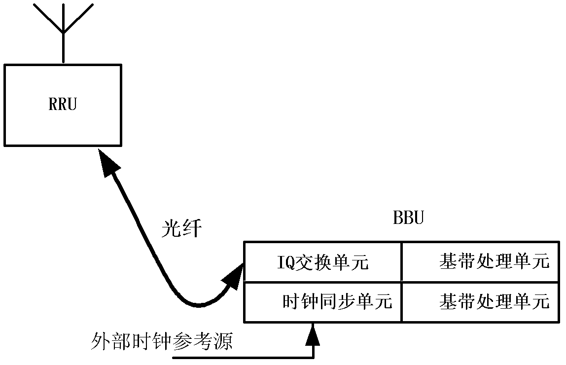
[0052] The wireless base station cluster system includes at least one BBU unit for IQ data exchange (hereinafter referred to as the exchange frame), multiple BBU units for baseband processing (hereinafter referred to as the baseband frame), and multiple RRU units. The switching frame includes components such as a clock synchronization unit and a plurality of IQ switching units, and may also include a baseband processing unit, or may not include a baseband processing unit. The baseband frame includes components such as a clock synchronization unit, a baseband processing unit, ...


PUM


Abstract

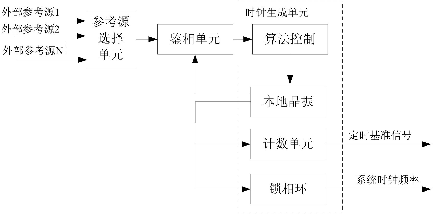
The invention provides a wireless base station clock synchronization method. The method comprises the following steps that: a frame is selected as an exchange frame from a wireless base station cluster system; the exchange frame generates a timing reference signal; the timing reference signal is coded in IQ data; the IQ data is sent to a base band frame; the base band frame recovers the timing reference signal from the IQ data, acquires a transmission time delay value of the base band frame and the exchange frame and compensates the recovered timing reference signal according to the transmission time delay value so that the compensated timing reference signal synchronizes with the timing reference signal of the exchange frame; the base band frame generates the timing reference signal which forms synchronization with itself according to the compensated timing reference signal. The invention also provides the wireless base station cluster system, the exchange frame and the base band frame. By using the method and the system, the wireless base station synchronization can be realized without increasing hardware and wiring resources.

Description

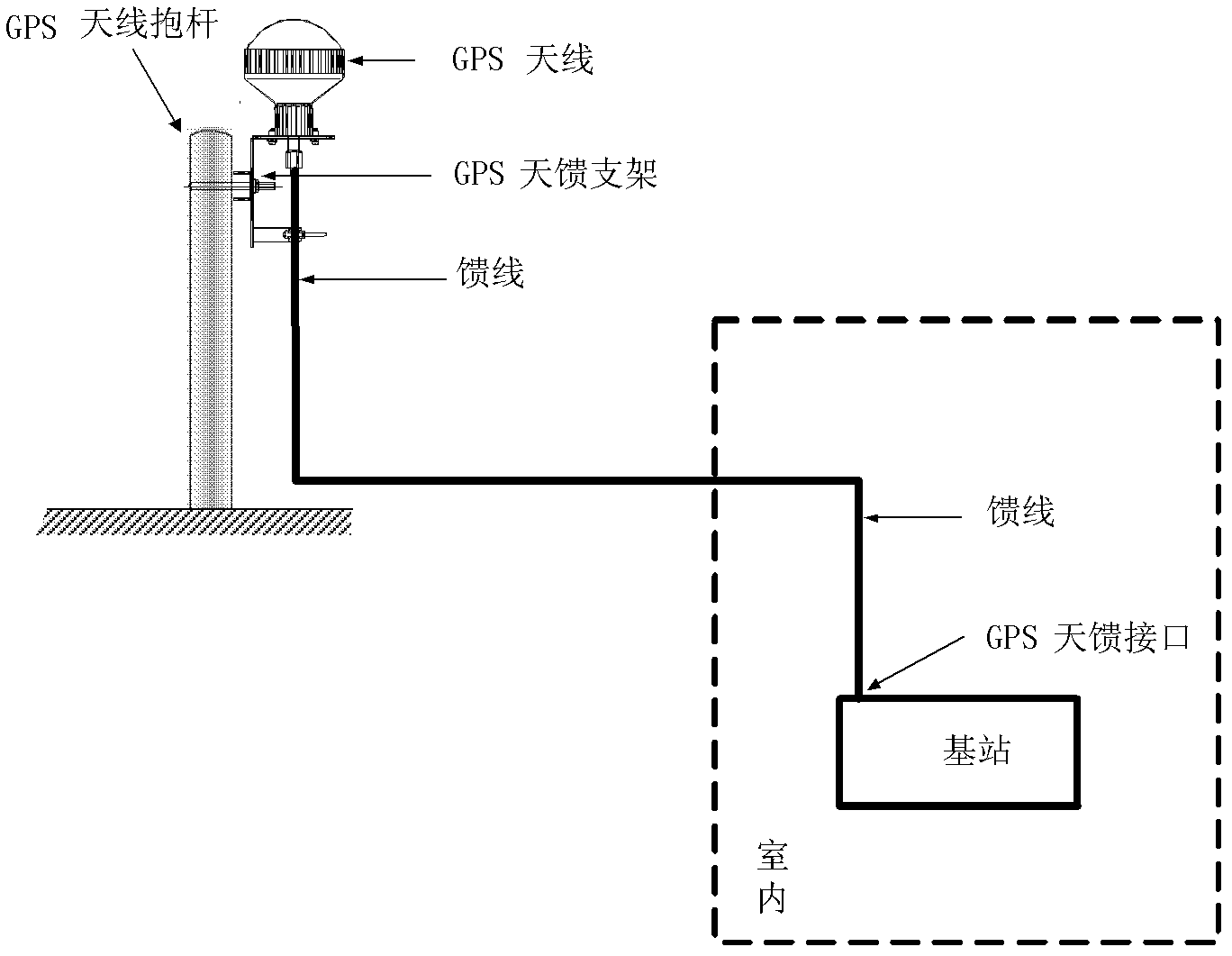
technical field [0001] The invention relates to the field of wireless communication, in particular to a clock synchronization method, system, baseband frame and switching frame of a wireless base station when a plurality of wireless base station clusters share a baseband pool. Background technique [0002] For wireless base stations, wireless base stations of some standards (such as CDMA / TD-SCDMA) require absolute alignment of time phases between base stations. For wireless base stations of some standards (such as GSM / UMTS), only base station system clock frequencies are basically equal, and time phase alignment is not required. For different clock requirements of the base station, clocks can be provided to the wireless base station through different timing schemes. For wireless base stations that require time and phase synchronization, timing schemes such as GPS can be used, such as figure 1 shown. For wireless base stations that do not need time phase synchronization, c...

Claims


Application Information

Patent Timeline
Patent Type & Authority Applications(China)
IPC IPC(8): H04W56/00H04L7/033H04L25/03
Inventor 傅小明邱文才
Owner ZTE CORP
Learn More