
Absorbent article

An absorbent, disposable technology, applied in the direction of absorbent pads, medical science, bandages, etc., can solve the problems of increased long fiber distance, reduced mobility, and difficulty in following expansion and contraction

Active Publication Date: 2012-01-11
KAO CORP
View PDF6 Cites 23 Cited by
  • Summary
  • Abstract
  • Description
  • Claims
  • Application Information

AI Technical Summary

Problems solved by technology

In this way, the hydrophilic fabric is formed of long fibers, so the distance between the long fibers increases due to the shrinkage of the elastic members during use, and the mobility of sweat in the hydrophilic fabric is reduced, and the shrinkage of the elastic members during use is repeated. , the long fibers are separated, it is difficult to follow the expansion and contraction, and there are cases where the mobility of sweat in the hydrophilic fabric is further reduced

Method used


Image

  • Absorbent article
  • Absorbent article
  • Absorbent article

Examples


Embodiment 1

[0111] Embodiment 1, use the hydrophilic hot air (air-through) non-woven fabric (25g / m2) that PP / PE and PET / PE fiber constitute as inner hydrophilic sheet 2 , width 60mm × width 100mm), as the outer hydrophilic sheet using 2 pieces of hydrophilic spunbonded non-woven fabrics made of PP fibers (10g / m 2 , 60mm in length and 120mm in width). In addition, 10 strands of natural rubber (470dtex) were used as waist elastic members. In Example 1, the inner hydrophilic sheet was placed on a flat surface, one of the outer hydrophilic sheets was placed on the inner hydrophilic sheet, and one of the outer hydrophilic sheets was placed side by side at intervals of 5 mm and stretched. For 10 waist elastic members with a stretch ratio of 200%, these waist elastic members are sandwiched, another outer hydrophilic sheet is provided, and one outer hydrophilic sheet and The other outer hydrophilic sheet is bonded all over, thereby forming the pleats.

[0112] The liquid spreading area of ​​ea...

Embodiment 2

[0114] Embodiment 2, use the weakly hydrophilic spun-bonded non-woven fabric (19g / m2) that PP fiber constitutes as the inside hydrophilic sheet 2 , width 60mm×width 100mm), as the outer hydrophilic sheet, use hydrophilic SMMS (spunbond / meltblown / meltblown / spunbond) composed of PP fibers (10g / m 2 , 60 mm in length x 120 mm in width), except that, in the same manner as in Example 1, pleats were produced.

[0115] The liquid diffusion area of ​​each of the inner hydrophilic sheet and the outer hydrophilic sheet used was measured in the same manner as in Example 1. The measured values ​​obtained are shown in Table 1. The measured value is the average value of n=5.

Embodiment 3

[0117] Embodiment 3, use the hydrophilic air-through non-woven fabric (36g / m 2 , width 60mm × width 100mm), as the outer hydrophilic sheet using a hydrophilic spun-bonded non-woven fabric composed of PP fibers (10g / m 2 , 60 mm in length x 120 mm in width), except that, in the same manner as in Example 1, pleats were produced.

[0118] The liquid diffusion area of ​​each of the inner hydrophilic sheet and the outer hydrophilic sheet used was measured in the same manner as in Example 1. The measured values ​​obtained are shown in Table 1. The measured value is the average value of n=5.


PUM


Abstract

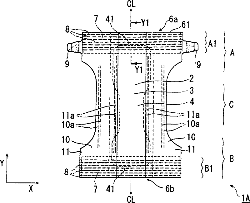
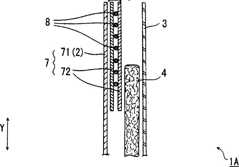
A disposable diaper (1A) is equipped with a central absorbent body (4) spanning from a back-side section (A) to an abdomen-side section (B), and with waist flaps (6a, 6b) having a hydrophilic sheet (7) disposed therein. The hydrophilic sheet (7) has an inner hydrophilic sheet (71) and an outer hydrophilic sheet (72) disposed on the side of a surface not in contact with the skin. The outer hydrophilic sheet (72) uses elements having greater liquid diffusion properties that the inner hydrophilic sheet (71). The inner hydrophilic sheet (71) and outer hydrophilic sheet (72) are disposed in a waist region (A1) that includes the region between the edge (61) of the wast flap (6a) on the back-side section (A) and the edge (41) of the absorbent body (4). On the waist flap (6a), gathers that extend in the width direction (X direction) of the diaper (1A) are formed in an elastic waist member (8) disposed within the waist flap (6a).

Description

technical field [0001] This invention relates to the absorbent article provided with the expansion-contraction part, such as a disposable diaper. Background technique [0002] At present, it is known to improve the distribution of sweat in the waist flaps (usually refers to the part from the absorbent main body including the absorbent core to the outside in the longitudinal direction) to prevent the occurrence of eczema, prickly heat, rash, etc. Disposable diapers. For example, Patent Document 1 discloses a disposable diaper in which an air-permeable sweat-absorbing sheet is bonded to the inner surface of the waistband. In addition, Patent Document 2 discloses a disposable diaper in which a hydrophilic fabric having long fibers arranged in the width direction is provided on the inner surface of the waistband portion. [0003] However, in the disposable diaper described in Patent Document 1, the sweat-absorbing sheet is formed of an upper layer including hydrophilic fibers ...

Claims


Application Information

Patent Timeline
Patent Type & Authority Applications(China)
IPC IPC(8): A61F13/49A61F13/496A61F13/511
CPCA61F13/49011A61F13/49466
Inventor 富田美奈奥田泰之
Owner KAO CORP
Learn More