Optical multi-level transmission system

一种传输系统、光电场的技术,应用在光信息传输领域,能够解决不能接收S极化成分电场信息等问题,达到改善接收灵敏度、信息量减少、提高的耐力的效果

Inactive Publication Date: 2012-01-11
HITACHI LTD
View PDF5 Cites 3 Cited by
  • Summary
  • Abstract
  • Description
  • Claims
  • Application Information

AI Technical Summary

Problems solved by technology

However, since the polarization state of the transmitted optical signal changes randomly during optical fiber transmission, part or all of the transmitted light may be transformed into orthogonal P-polarized waves, so that the coherent optical field receiver front end 100-1 cannot Receive the electric field information of the S polarization component

Method used


Image

  • Optical multi-level transmission system
  • Optical multi-level transmission system
  • Optical multi-level transmission system

Examples


Embodiment Construction

[0103] Figure 5 It is a block diagram showing a phase pre-accumulation type incoherent optical multivalued transmission system according to the first embodiment of the present invention.

[0104] Hereinafter, paths of optical signals are indicated by thick lines, paths of electrical signals are indicated by thin lines, and paths of parallel digital electrical signals using a plurality of signal lines are indicated by hollow arrows. This structure is an incoherent optical multi-value transmission system using a phase pre-accumulation optical field transmitter 200 and an incoherent optical field receiver 220 .

[0105] Figure 4 The first difference between the shown prior art and this embodiment lies in the symbol judgment circuit inside the incoherent optical field receiver 220. In this embodiment, the amplitude-weighted non-Euclidean distance is used Symbol judging circuit 233.

[0106] Figure 4 The second point of difference between the shown prior art and the present ...


PUM


Abstract

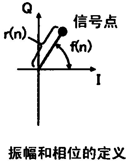
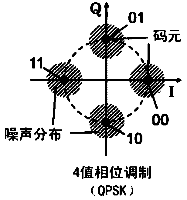
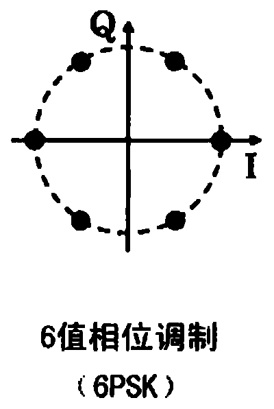
Provided is an optical multilevel transmission system, comprising at least one optical multilevel transmitter for transmitting an optical multilevel signal obtained and an optical multilevel receiver for receiving the optical multilevel signal. The received optical multilevel signal has a larger noise in an angular direction than in a radial direction. The optical multilevel receiver sets, in a symbol decision of the received optical multilevel signal demodulated on the complex plane, for positions of all or some of ideal signal points, a width in the angular direction of a decision area, to which each of the ideal signal points belongs and which is measured along a circumference of a circle centered at an origin and passing through a center of the each of the ideal signal points, larger than a width in the angular direction of a decision area defined based on a Euclidean distance.

Description

technical field [0001] The invention relates to optical information transmission technology, in particular to an optical field transmitter and an optical field transmission system suitable for sending and receiving multi-valued optical information transmitted by optical fiber. Background technique [0002] As the number of wavelengths increases or the modulation speed of optical signals increases, the amount of information (transmission capacity) that can be transmitted with one optical fiber basically uses up the wavelength band of the optical fiber amplifier and has reached its limit. In addition, in order to increase the transmission capacity of the optical fiber, it is necessary to study a signal modulation method, and load multiple optical signals in a limited frequency band to improve the utilization efficiency of the frequency band. [0003] In the world of wireless communication, since the 1960s, it has been possible to perform high-efficiency transmission with a fre...

Claims


Application Information

Patent Timeline
Patent Type & Authority Applications(China)
IPC IPC(8): H04L27/36H04B10/04H04B10/06H04B10/14H04B10/142H04B10/152H04B10/26H04B10/28H04B10/50H04B10/54H04B10/67H04B10/69
CPCH04B10/676H04L27/3845H04B10/541H04L25/061H04B10/695H04B10/5055
Inventor 菊池信彦
Owner HITACHI LTD
Why Eureka
Try Eureka