Shear box device for rock indoor direct shear test

A shear box and rock technology, applied in the field of rock mechanics, can solve problems such as the inability to guarantee the geometric center of the shear load, not shearing, and test failure, etc., and achieve the effects of simple structure, convenient operation, and wide applicability

Inactive Publication Date: 2012-01-18
INST OF ROCK AND SOIL MECHANICS - CHINESE ACAD OF SCI
View PDF5 Cites 15 Cited by
  • Summary
  • Abstract
  • Description
  • Claims
  • Application Information

AI Technical Summary

Problems solved by technology

In the current rock laboratory direct shear test, the upper shear cell is directly covered on the rock sample, and the rock sample will be compressed and deformed under the normal load. In order to ensure that the normal load can be transmitted to the rock sample rather than by The shear box is responsible, and a shear joint of a certain width must be reserved between the upper and lower shear boxes.

Method used


Image

  • Shear box device for rock indoor direct shear test
  • Shear box device for rock indoor direct shear test

Examples


Example Embodiment

[0011] The present invention will be further explained below in conjunction with the drawings.

[0012] see Attachment.
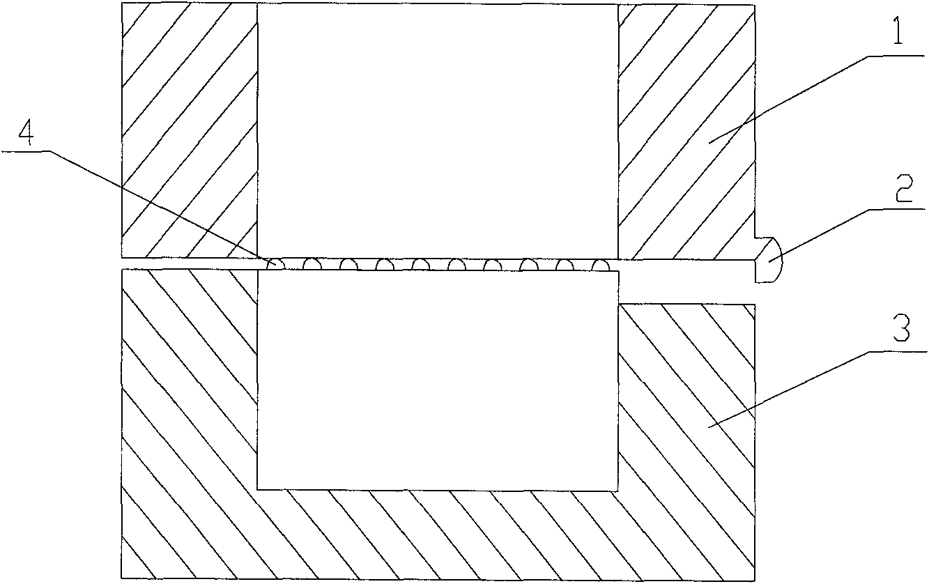
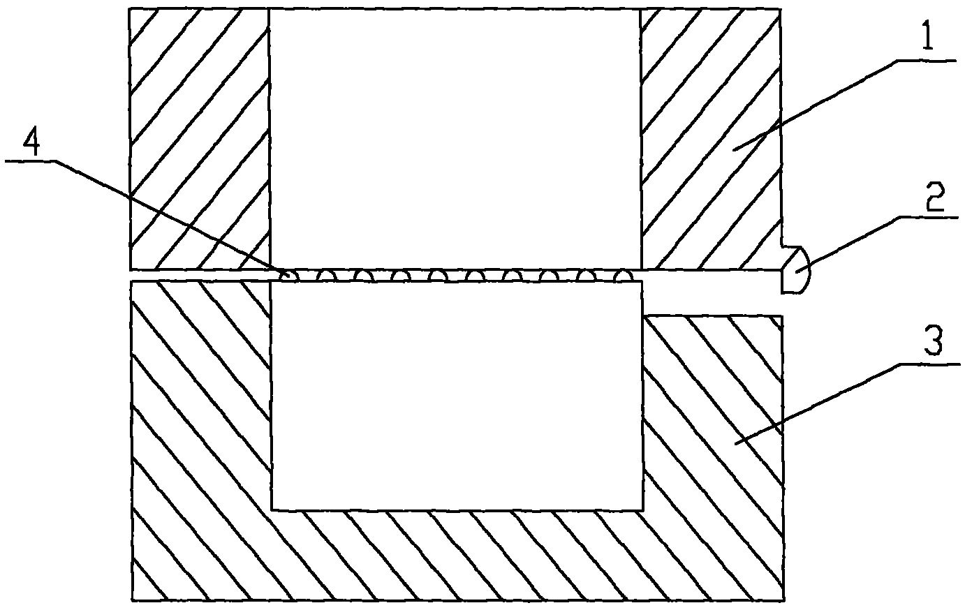
[0013] The shear box device for the direct shear test in the rock room includes an upper shear box 1 and a lower shear box 3. The lower shear box 3 is a square box without an upper cover. The material is made of high-strength steel. The side wall of the box along the direction of the shearing movement is notched to leave room for the shear displacement. There are tension shafts on the front and rear outer walls of the box body of the box 3, and the shear load is applied through the tension shafts during the test. The top of the two walls of the lower shear box 3 front and rear are provided with grooves, and the grooves are respectively inlaid with in-line ball rows. 4. The height of the in-line ball row 4 protruding from the top surface of the lower shear box 3 is ≤1mm, and the length of the in-line ball row 4 is the same as the length of the two inner walls of...


PUM

PropertyMeasurementUnit
Heightaaaaaaaaaa

Abstract

The invention relates to a rock indoor direct shear test technology, more concretely relates to a shear box device for a rock indoor direct shear test, and belongs to the rock mechanics technical field. The shear box device for the rock indoor direct shear test comprises an upper shear box device and a lower shear box device, a pair of in-line ball rows are provided between the upper shear box device and the lower shear box device, the pair of in-line ball rows are mutually paralleled which are inlaid in the grooves on the top of the front and back wall surfaces of the lower shear box. The shear box device changes a traditional shear box structure, because the upper shear box uses a half-headed mode during the direct shear test, the problem that the width of the shearing seam can not be controlled due to the sample sizes and processing differences is solved, the arrangement of the in-line ball rows realizes the positioning of shear plane of the rock samples and avoids the phenomenon of twist-off but not shear-off of samples. The shear box device of the invention has the advantages of simple structure, easy manufacture, convenient operation and wide application.

Description

technical field [0001] The invention relates to a rock indoor direct shear test technology, more specifically to a shear box device for a rock indoor direct shear test, and belongs to the technical field of rock mechanics. Background technique [0002] Indoor direct shear tests on rocks and structural surfaces usually use the horizontal push method. The rock sample is placed in the lower shear box, the upper shear box is covered on the rock sample, and a certain width is reserved between the upper and lower shear boxes. A normal load is applied to the upper shear box, and a shear load is applied to the lower shear box to cause shear failure of the rock sample and measure its shear strength. [0003] According to the relevant national test specifications, when performing a direct shear test, the acting direction of the normal load and the shear load should pass through the geometric center of the predetermined shear plane of the rock sample. In the current rock laboratory di...

Claims


Application Information

Patent Timeline
IPC IPC(8): G01N3/02G01N3/24
Inventor 高红艾东海胡元育
Owner INST OF ROCK AND SOIL MECHANICS - CHINESE ACAD OF SCI
Why Eureka
Try Eureka