Linear accelerometer with zero self compensation

A linear acceleration and accelerometer technology, applied in the field of sensors, can solve the problems of high cost, the size of the zero position of the accelerometer and the long-term stability performance change of the zero position, and complex principles, so as to reduce the application cost, implement simple and convenient, realize The effect of zero self-compensation

Active Publication Date: 2012-01-18
FLIGHT AUTOMATIC CONTROL RES INST
View PDF5 Cites 7 Cited by
  • Summary
  • Abstract
  • Description
  • Claims
  • Application Information

AI Technical Summary

Problems solved by technology

[0004] From the composition and principle of the existing high-precision accelerometer figure 1 It can be seen that since the moving plate and the fixed plate that determine the capacitance in the capacitive signal sensor are mechanically connected or glued, as time goes by or the temperature changes, the moving plate and the fixed plate will be deformed, and the mechanical connection will also be damaged. Will change or glue deformation, change the capacitance of the sensor, change the size of the zero position of the accelerometer and the long-term stability of the zero position
[0005] In order to meet the zero size requirements of the accelerometer and improve the long-term stability of the zero position, it can be concluded from information at home and abroad that, on the one hand, the user needs to re-calibrate the accelerometer and the user system repeatedly when using the accelerometer, which has poor reliability. And the cost is high; on the other hand, develop a new type of accelerometer, including: improving the magnetic circuit (using high magnetic rare earth permanent magnet materials and improving temperature stability, etc.), selecting a new signal sensor, improving the flexible hinge, optimizing the electronic circuit and increasing temperature compensation etc., the accelerometer produced in this way has complex principles, high cost, large volume and poor reliability

Method used


Image

  • Linear accelerometer with zero self compensation
  • Linear accelerometer with zero self compensation
  • Linear accelerometer with zero self compensation

Examples


Embodiment 1

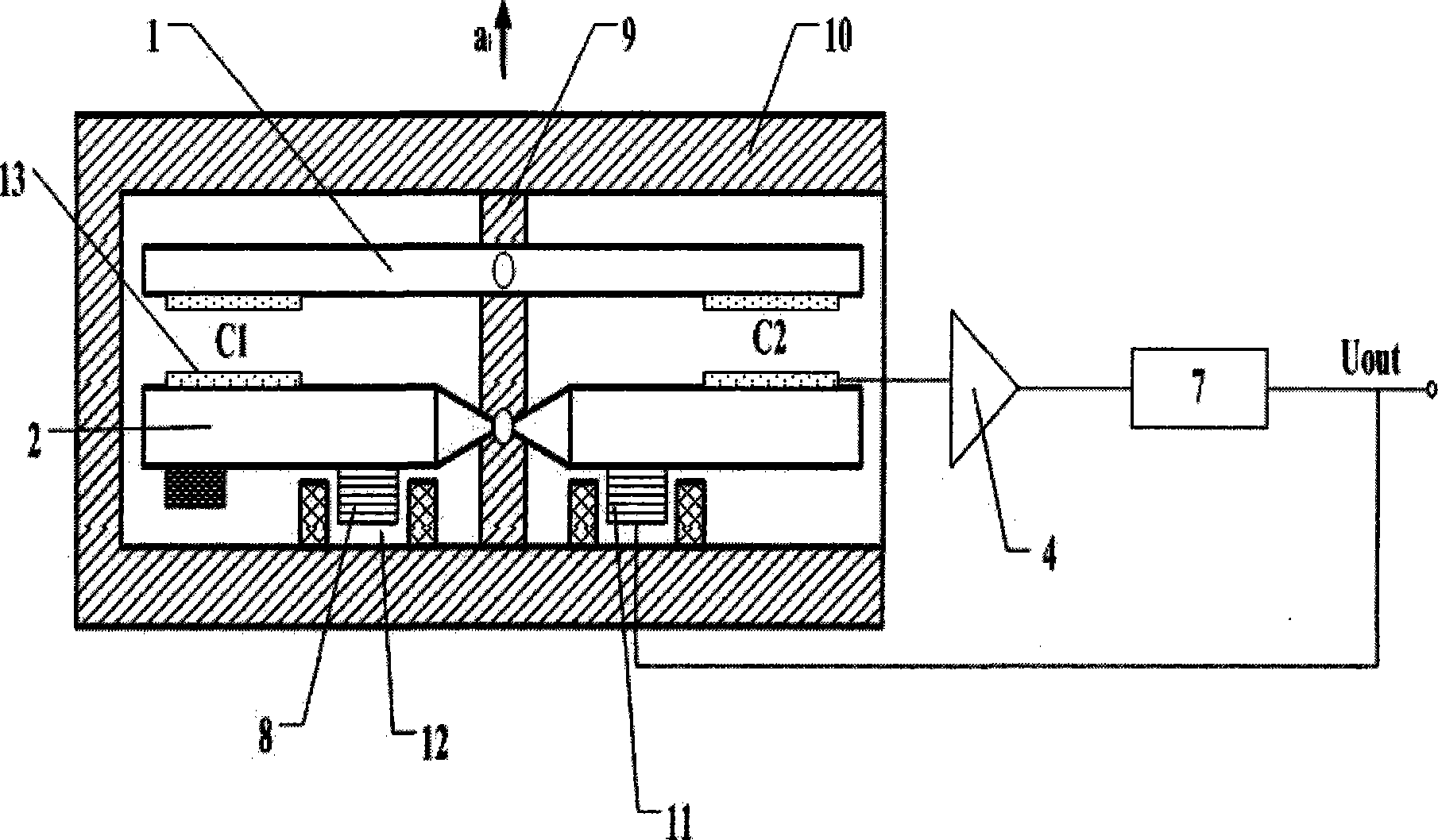
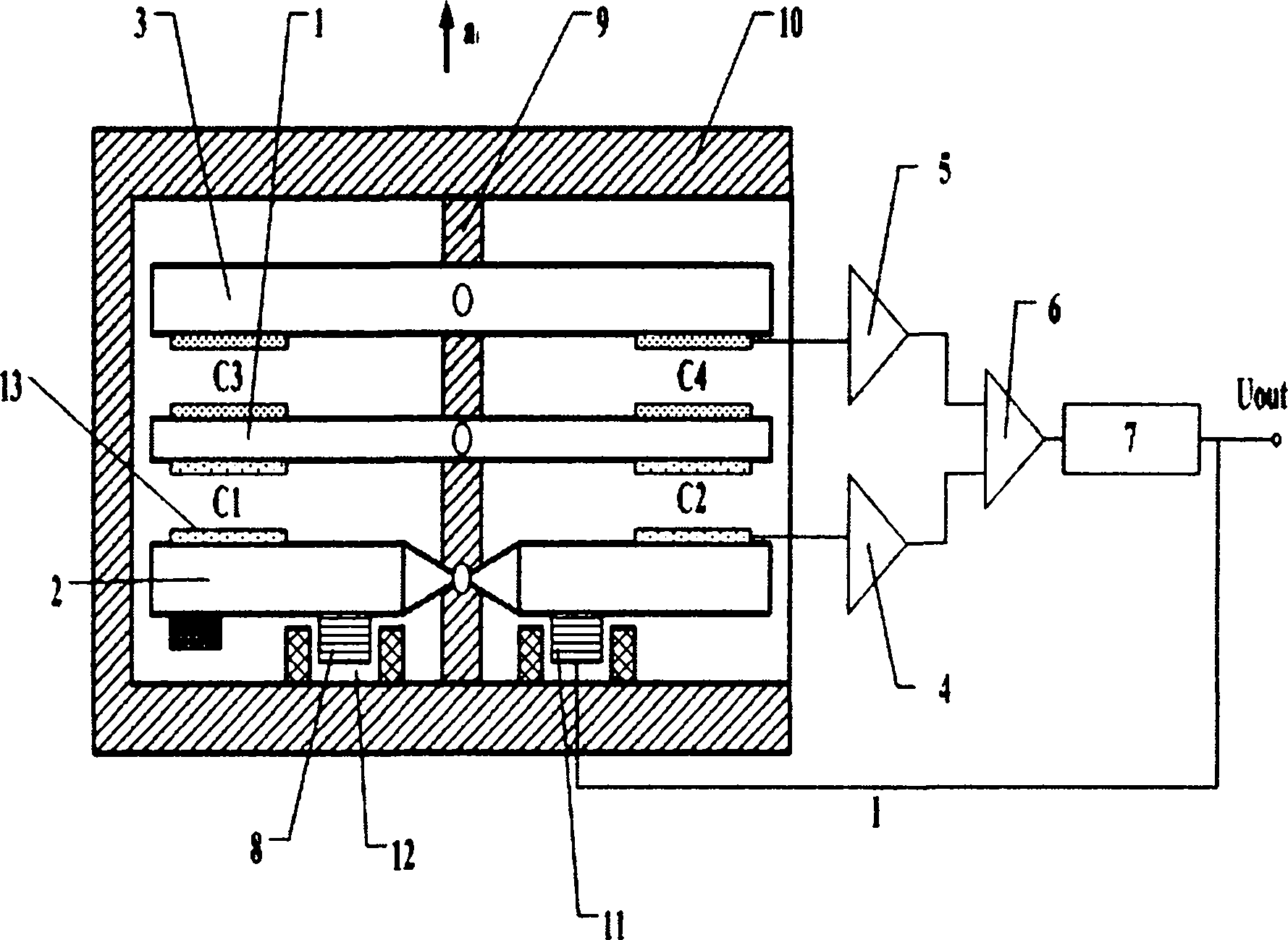
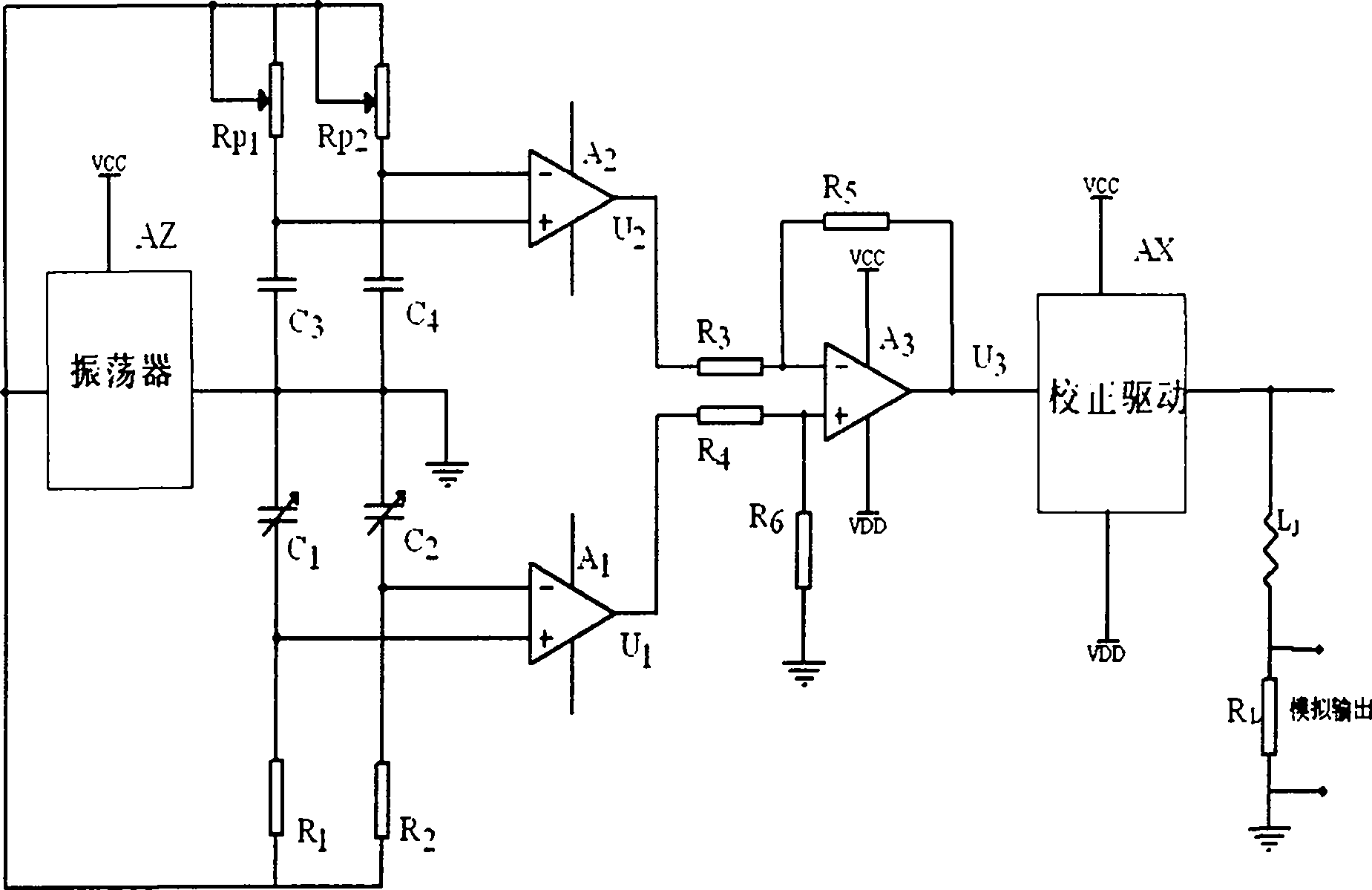
[0020] The C formed by the electrode plate on the capacitor fixed plate 1 and the capacitor moving plate 2 1 、C 2 The variation range of the capacitor is 0∽100pF, the capacitor C formed by the electrode plate on the capacitance fixed plate 1 and the electrode plate on the capacitance detection plate 3 3 =C 4 =50pF,R 1 = R 2 =100kΩ, Rp 1 =Rp 2 = 150kΩ, R 3 = R 4 = R 5 = R 6 =10kΩ, sampling resistor R L =1kΩ, fix the accelerometer on the mechanical dividing head, turn the dividing head so that the input acceleration of the accelerometer is 0g, and use a digital voltmeter to detect the sampling resistance R L The terminal voltage value is 11mv, adjust the capacitance pickup circuit 5 to detect Rp in the bridge 2 The size of the resistance, so that the sampling resistor R L The terminal voltage value is reduced from 11mv to 0.101mv to realize the adjustment of the zero position;

[0021] Fix the accelerometer in a high and low temperature test box with a stable measur...


PUM


Abstract

The invention belongs to the technical field of sensors, and relates to a linear accelerometer with zero self compensation. The accelerometer comprises a capacitor fixed plate, a capacitor movable plate, a capacitor detection pole plate, two capacitor pick-up circuits, a compensating circuit, a correction drive circuit, a torque, a fixed column and a housing. On the basis of unchanging the traditional accelerometer principle, the capacitor detection pole plate and the compensation circuit are additionally provided, so that the change of accelerometer zero position size, caused by time lapse or temperature change, can be automatically compensated. The linear accelerometer has the advantages of simple principle, convenience for implementation, low cost and high reliability, and can meet thedemands of systems such as inertial navigation, inertial guidance and the like on accelerometer zero position size and zero position long-term stability performance.

Description

technical field [0001] The invention belongs to the technical field of sensors and relates to a zero-position self-compensating linear accelerometer. Background technique [0002] The accelerometer is one of the core sensitive elements in inertial navigation, inertial guidance, and flight automatic control systems. It is used to measure constant and low-frequency acceleration a acting along its input axis i , whether in aerospace, or in other technical fields have been widely used. Inertial-grade accelerometers are often closed-loop pendulum structures, which are mainly composed of signal sensors, torque converters, and rebalance circuits. At present, the signal sensor of high-precision accelerometer generally adopts capacitive type, for example, the US QA3000 accelerometer sensor used in tactical and strategic missiles is capacitive type. The composition and principle of the existing high-precision accelerometer see figure 1 . In this figure the capacitor C 1 、C 2 The...

Claims


Application Information

Patent Timeline
Patent Type & Authority Applications(China)
IPC IPC(8): G01P15/125
Inventor 张尧舜肖卫民
Owner FLIGHT AUTOMATIC CONTROL RES INST
Why Eureka
Try Eureka