Method for calibrating phase center of receiver antenna and apparatus thereof

A technology of antenna phase center and phase center, which is applied in the field of communication, can solve problems such as not being able to obtain absolute positioning, and achieve the effect of correcting measurement errors

Active Publication Date: 2012-01-18
北京华力创通科技股份有限公司
View PDF3 Cites 37 Cited by
  • Summary
  • Abstract
  • Description
  • Claims
  • Application Information

AI Technical Summary

Problems solved by technology

[0006] The disadvantages of the method for calibrating the variation of the phase center of the receiver antenna in the above-mentioned prior art are: 1) directly receive the navigation star signal, and obtain the PCO and PCV of the receiver antenna by changing the baseline vector with the reference antenna. Relative positioning, absolute positioning cannot be obtained; 3) When measuring in the open interval, external random factors introduce various errors, which will limit the further improvement of calibration accuracy; 2) Direct far-field microwave testing is not possible like microwave testing due to test methods and practical limitations. As much calibration information (data) as can be obtained with near-field measurement methods

Method used


Image

  • Method for calibrating phase center of receiver antenna and apparatus thereof
  • Method for calibrating phase center of receiver antenna and apparatus thereof
  • Method for calibrating phase center of receiver antenna and apparatus thereof

Examples


Embodiment 1

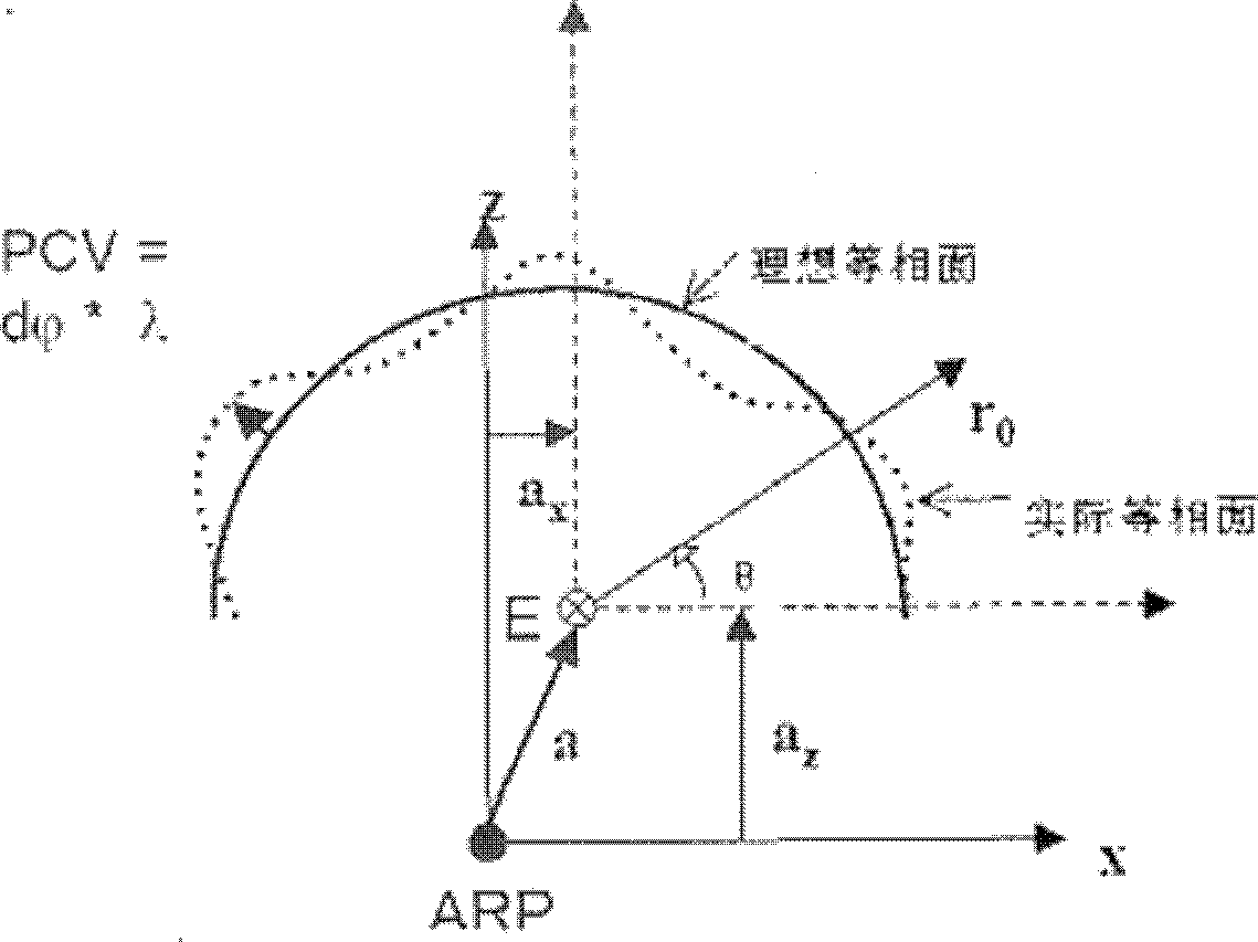
[0024] Calibrating the variation of the phase center of the receiver antenna includes two parts: the calibration and calibration of the PCO relative to the antenna reference point ARP (the center of rotation of the turntable), and the calibration and calibration of the PCV relative to the PCO.

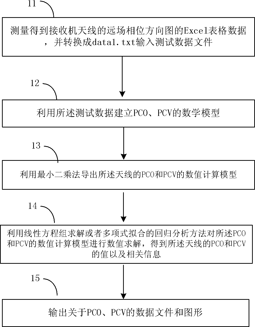
[0025] The processing flow of a method for calibrating the variation of the phase center of the receiver antenna provided by this embodiment is as follows: figure 1 As shown, including the following processing procedures:

[0026] Step 11, measure and obtain the Excel table data of the far-field phase pattern of the receiver antenna, and convert it into a data 1.txt input test data file.

[0027] The far-field phase pattern data of the receiver antenna is measured by using the far-field test method or the near-field test method. - Calculated by far-field transformation software. Using the far-field phase pattern data as input test data for the method;

[0028] The above far-field ph...

Embodiment 2

[0080] The difference between this embodiment and the first embodiment is that the processing procedure of step 14 in the first embodiment is modified, and other processing steps are the same as those in the first embodiment.

[0081] The modification to the processing procedure of step 14 in the first embodiment is as follows: after using the least squares method to derive the numerical calculation model of the PCO and PCV of the antenna, use the regression analysis method of polynomial fitting to analyze the numerical values ​​of the PCO and PCV The calculation model is numerically solved, and the values ​​of PCO and PCV of the antenna can also be obtained.

[0082] The process of using polynomial fitting to achieve least squares fitting is as follows: Take a linear fitting as an example; assume:

[0083] x 1 = sinθ i cosφ j ; x 2 = sinθ i sinφ j ; x 3 =cosθ i ;

[0084] i=1, 2,...n, j=1...m

[0085] where x 1 , x 2 , x 3 is the input variable and y is the out...

Embodiment 3

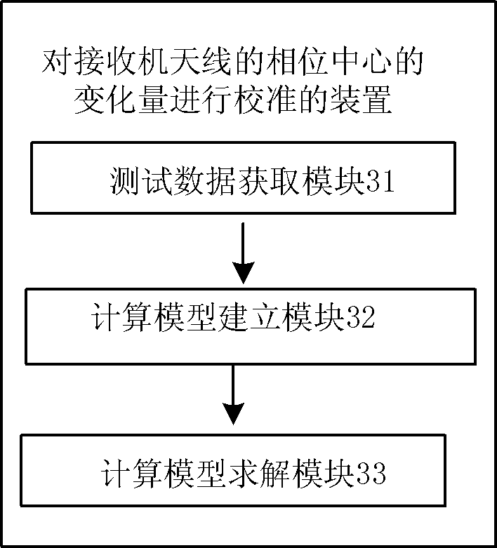
[0106] The embodiment of the present invention also provides a device for calibrating the variation of the phase center of the receiver antenna, the specific structure of which is as follows image 3 As shown, the following modules are included:

[0107] The input test data acquisition module 31 is used to measure and obtain the far-field phase pattern data of the receiver antenna, and use the far-field phase pattern data as input test data;

[0108] Mathematical model building module 32, for utilizing described input test data to set up the mathematical model of the average phase center PCO of described receiver antenna, antenna phase center dispersion degree PCV;

[0109] The mathematical model solving module 33 is used to derive the numerical calculation model of the PCO and PCV of the antenna by the least square method, and perform numerical calculation on the numerical calculation model of the PCO and PCV by using the linear equation solution or the regression analysis me...


PUM


Abstract

An embodiment of the invention provides a method for calibrating a phase center of a receiver antenna and an apparatus thereof. The method comprises the following steps: measuring and obtaining far field phase directional diagram data of a receiver antenna and taking the far field phase directional diagram data as input test data; establishing mathematical models of Phrase Center Offset (PCO) andPhase Center Variation (PCV) of the receiver antenna by utilizing the input test data; exporting PCO and PCV value calculation models of the antenna by utilizing a least square method, and carrying out numerical solution on the PCO and PCV value calculation models by utilizing a linear equation group solution or polynomial fitting regression analysis method to obtain PCO and PCV values of the antenna. According to the embodiment of the invention, absolute positioning (phase) of PCO and PCV of the receiver antenna can be obtained, and a measurement error brought by antenna phase center change can be accurately corrected to raise measurement precision of a GNSS (Global Navigation Satellite System) receiver.

Description

technical field [0001] The invention relates to the technical field of communication, in particular to an application occasion with strict requirements on the phase center of a receiver antenna. The invention provides a microwave measurement and data processing method and device for accurately calibrating the antenna phase center. Background technique [0002] At present, satellite navigation systems such as GPS (Global Positioning System, Global Positioning System), GNSS (Global Navigation Satellite System, Global Navigation Satellite System), GALILEO (Galileo) and my country's 'Beidou' navigation satellite series all have navigation and positioning functions, and gradually form Diversified space resource environment. [0003] Positioning and measurement are the two major functions of the satellite navigation system. Positioning uses the pseudo-code phase as the observation to determine the pseudo-range, and measurement determines the pseudo-range based on the carrier phase...

Claims


Application Information

Patent Timeline
Patent Type & Authority Applications(China)
IPC IPC(8): G01R29/10
Inventor 叶云裳姜新发苑九功钟睿黄夔夔那成亮李光成
Owner 北京华力创通科技股份有限公司
Why Eureka
Try Eureka