Small-current failure location system

A technology of fault location and small current, applied in the direction of fault location, etc., can solve problems such as loss of feeder automation, heavy burden on the main station, economic loss, etc.

Inactive Publication Date: 2012-01-18
STATE GRID ZHEJIANG NINGBO YINZHOU POWER SUPPLY LTD CO
View PDF5 Cites 2 Cited by
  • Summary
  • Abstract
  • Description
  • Claims
  • Application Information

AI Technical Summary

Problems solved by technology

[0003] The conventional FA implementation mode is the centralized control type, which requires a communication channel and a control master station. When a fault occurs, the master station receives the information sent by the feeder terminal unit (Feeder Terminal Unit, FTU), and locates the fault through software calculation based on the information , and automatically send remote control commands to the switch to achieve the purpose of isolating faults and restoring power supply. However, in this control mode, receiving fault information, locating faults and issuing control commands are all operated by the master station, so , the burden on the master station is heavy, and the speed of troubleshooting is slowed down. At the same time, the FTU uploads information to the master station, and the master station sends control information to the FTU. The information needs to be transmitted back and forth between the master station and the FTU,

Method used


Image

  • Small-current failure location system
  • Small-current failure location system

Examples


Embodiment Construction

[0017] The following will clearly and completely describe the technical solutions in the embodiments of the present invention with reference to the accompanying drawings in the embodiments of the present invention. Obviously, the described embodiments are only some, not all, embodiments of the present invention. Based on the embodiments of the present invention, all other embodiments obtained by persons of ordinary skill in the art without making creative efforts belong to the protection scope of the present invention.

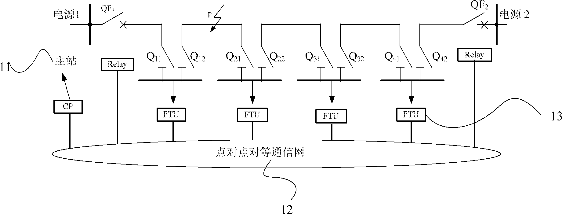
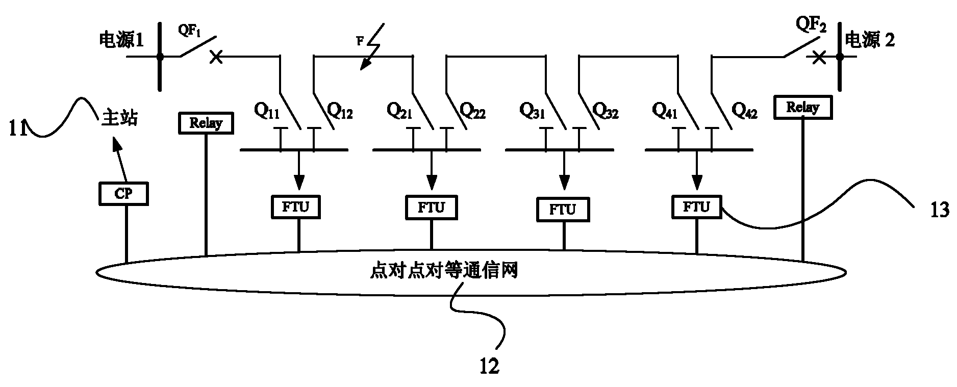
[0018] The invention discloses a system for realizing fault self-healing, please refer to figure 1 , including master station 11, point-to-point peer-to-peer communication network 12 and power distribution automation terminal FTU 13; FTU 13 accesses point-to-point peer-to-peer communication network; master station 11 accesses point-to-point communication through a communication processor (Communication Processor, CP) network 12; the point-to-point peer-to-peer...


PUM


Abstract

The invention discloses a small-current failure location system which comprises a main station, a peer-to-peer communication network and distribution automatic terminal FTUs (Feed Terminal Unit), wherein the FTUs access the peer-to-peer communication network; the main station access a peer-to-peer network through a communication processor; the peer-to-peer communication network is used for realizing peer-to-peer communication between adjacent FTUs; each FTU comprises a failure receiving unit used for receiving failure information reported by the FTU, an incoming line failure judging unit used for judging whether an incoming line of a looped network cabinet corresponding to the FTU fails, a unit for judging failure between adjacent looped network cabinets, and a unit for determining failure of a bus between the looped network cabinets, wherein the unit for judging the failure between the adjacent looped network cabinets is used for delaying time Ti, receiving failure information of adjacent FTUs through the peer-to-peer network and judging whether looped network cabinets corresponding to the adjacent FTUs fail when the incoming line failure judging unit judges that two incoming lines fail; and the unit for determining the failure of the bus between the looped network cabinets is used for determining that the type of the failure is the failure of the bus between the looped network cabinet when the unit for judging the failure between the adjacent looped network cabinets judges that the looped network cabinets corresponding to the adjacent FTUs do not fail.

Description

technical field [0001] The invention relates to the technical field of power system automation, in particular to a small current fault location system. Background technique [0002] At present, in order to reduce the fault time of the medium-voltage power grid, the feeder automation (FA) has been widely paid attention to. FA refers to the automation of feeder lines between substation outlets and user equipment. It is used for user detection, data measurement, and operation optimization under normal conditions, as well as fault detection, fault isolation, transfer, and restoration of power supply control under accident states. [0003] The conventional FA implementation mode is the centralized control type, which requires a communication channel and a control master station. When a fault occurs, the master station receives the information sent by the feeder terminal unit (Feeder Terminal Unit, FTU), and locates the fault through software calculation based on the information ...

Claims


Application Information

Patent Timeline
IPC IPC(8): G01R31/08
Inventor 胡杰王吉庆高颂九凌荣光李光军张彦郑坤力李金海张惠芳胡余坚黄继明
Owner STATE GRID ZHEJIANG NINGBO YINZHOU POWER SUPPLY LTD CO
Why Eureka
Try Eureka