

Line array multi-channel synchronous transient electromagnetic directional detection method and device thereof
A transient electromagnetic and multi-channel synchronization technology, which is applied in the direction of electromagnetic wave detection, radio wave directional device components, and radio wave direction finders, can solve the problem of poor contrast, affecting resolution and interpretation, and unrecognizable abnormalities Signal and other issues, to achieve the effect of strong signal comparability, improved reliability, and high signal-to-noise ratio
- Summary
- Abstract
- Description
- Claims
- Application Information
AI Technical Summary
Problems solved by technology
Method used
Image

Examples
Embodiment Construction
[0024] The present invention will be further described below in conjunction with the accompanying drawings and specific embodiments.
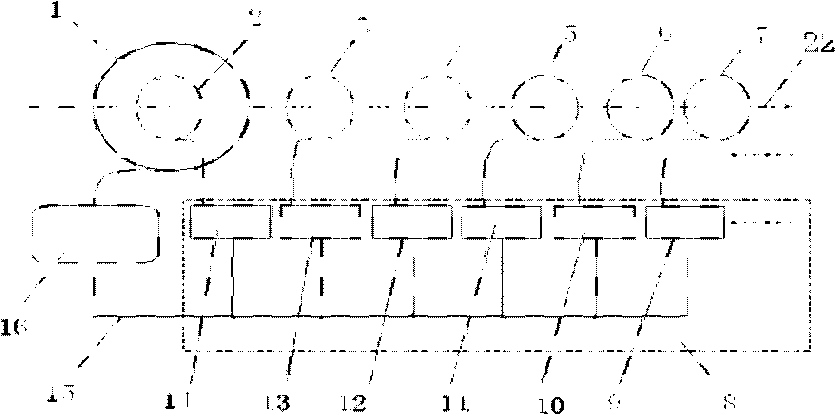
[0025] see image 3 , the synchronization signal of the multi-channel synchronous acquisition system 8 is connected to the transient electromagnetic transmitter 16 through the synchronous control of the wire 15, and the multi-channel synchronous acquisition system is composed of the first synchronous receiving and collecting device 14, the second synchronous receiving and collecting device 13, the third synchronous The receiving and collecting device 12, the fourth synchronous receiving and collecting device 11, the fifth synchronous receiving and collecting device 10, and the sixth synchronous receiving and collecting device 9 are composed of 6 synchronous receiving and collecting devices connected in parallel, and the first synchronous receiving and collecting device 14 is provided with a first receiving and collecting device. Wire frame 2, t...
PUM
 Abstract
Description
Claims
Application Information