Voltage transforming rectifier with dual functions of voltage stabilization and harmonic injection

A technology of transformer rectifier and harmonic injection, which is applied in the direction of output power conversion device, conversion of DC power input to DC power output, conversion of AC power input to DC power output, etc., which can solve the problems of reduced reliability, increased volume and weight, etc. problem, to achieve the effect of increased reliability, reduced harmonic content, and reduced harmonic content

Inactive Publication Date: 2012-01-18
NANJING UNIV OF AERONAUTICS & ASTRONAUTICS
View PDF4 Cites 10 Cited by
  • Summary
  • Abstract
  • Description
  • Claims
  • Application Information

AI Technical Summary

Problems solved by technology

[0006] The purpose of the present invention is to overcome the deficiencies in the prior art and provide a transformer rectifier device with dual functions of output voltage stabilization and reduction of input current harmonic content through harmonic injection method, so as to solve the problem of traditional transformer rectifiers due to the direct increase of the voltage stabilization circuit. The disadvantages of circuit complexity, greatly increased volume and weight and reduced reliability brought about by the harmonic injection circuit

Method used


Image

  • Voltage transforming rectifier with dual functions of voltage stabilization and harmonic injection
  • Voltage transforming rectifier with dual functions of voltage stabilization and harmonic injection
  • Voltage transforming rectifier with dual functions of voltage stabilization and harmonic injection

Examples


Embodiment Construction

[0018] The technical solutions of the present invention will be further described below in conjunction with the accompanying drawings and embodiments.

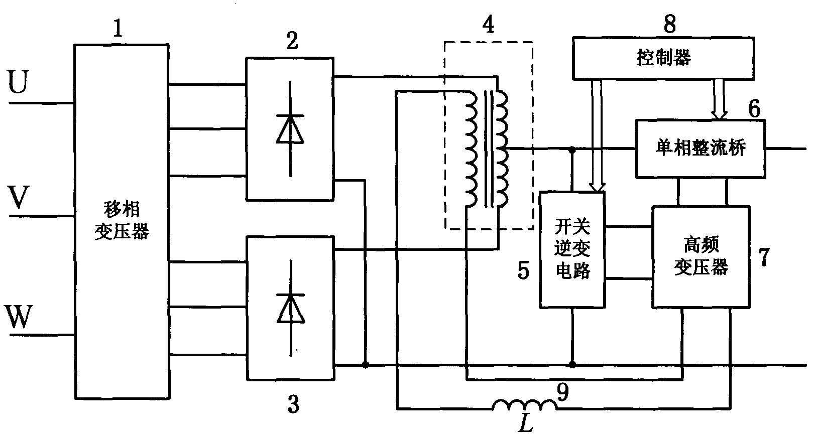
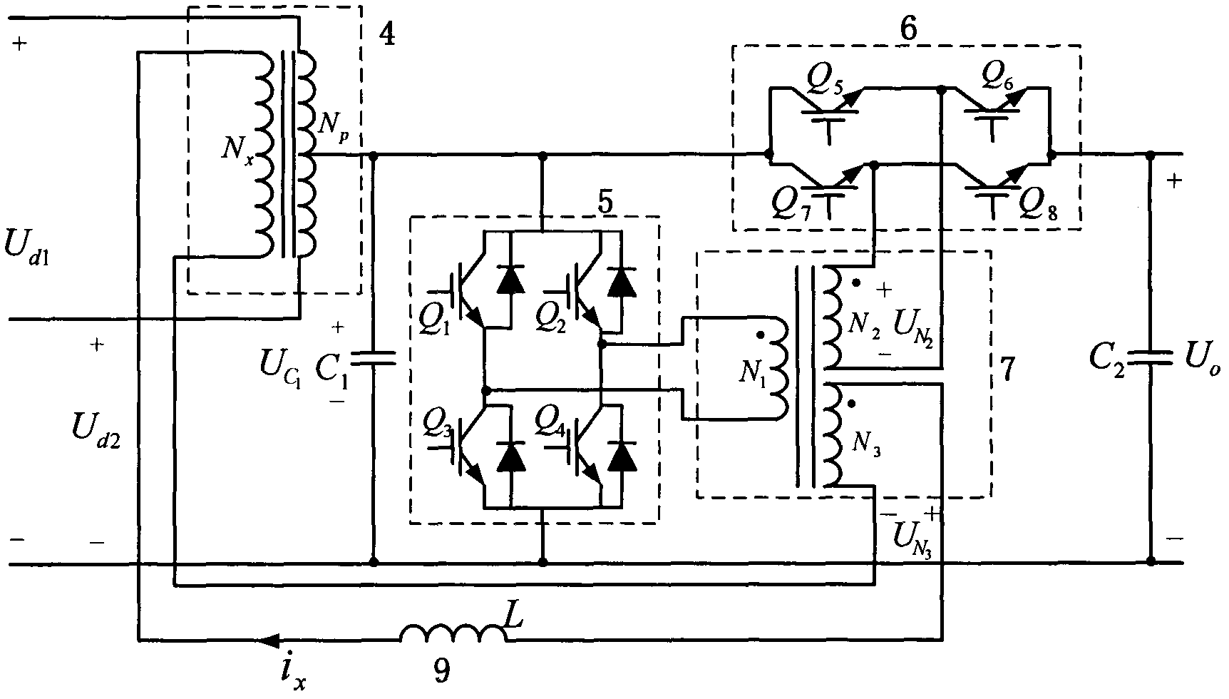
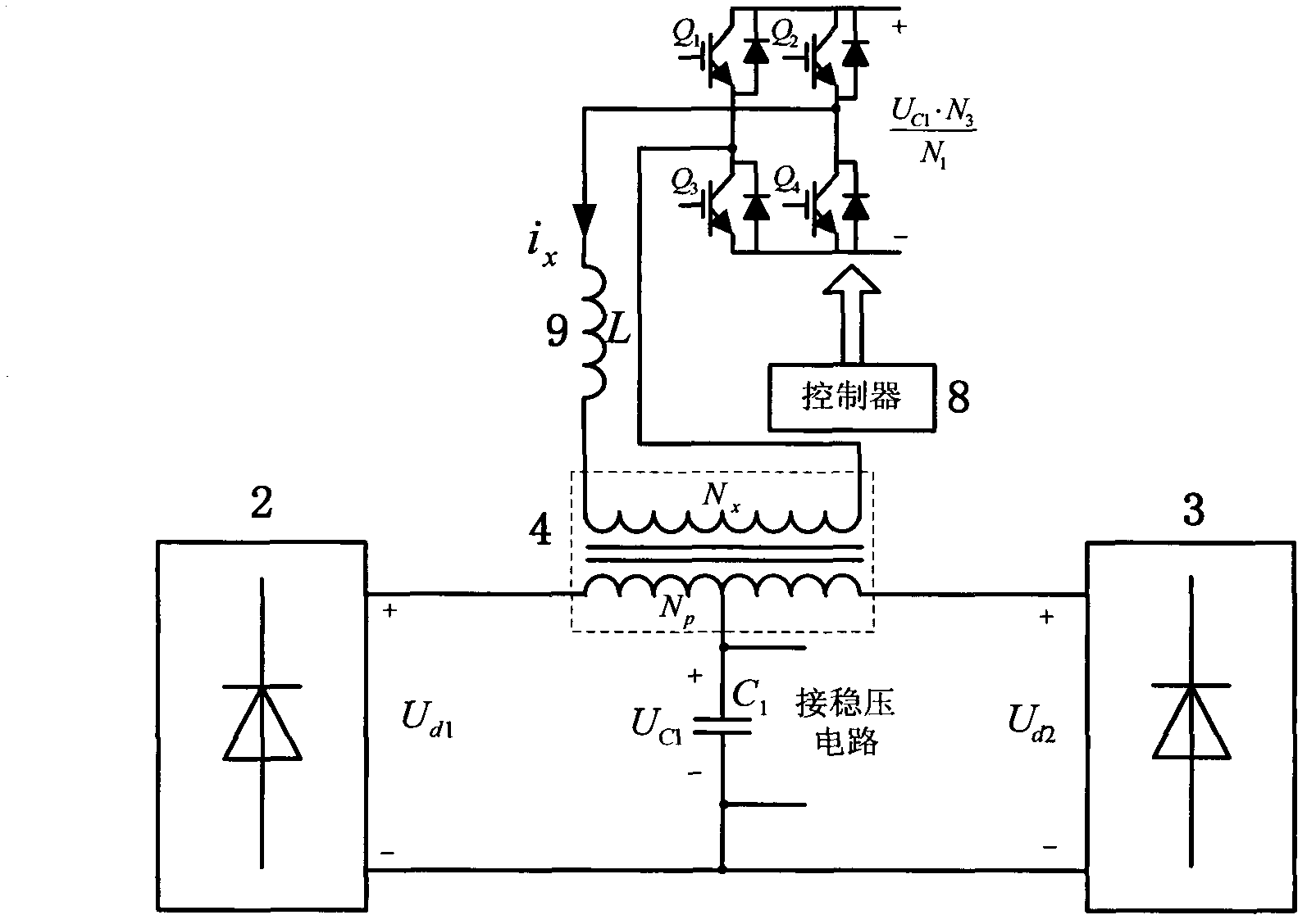
[0019] This example takes the input of three-phase 115V / 400Hz AC and 12-pulse transformer rectifier as an example for illustration. The block diagram of the main circuit structure of the transformer rectifier with dual functions of voltage stabilization and harmonic injection is shown in figure 1 As shown, it is characterized in that: its circuit structure consists of a phase-shifting transformer 1, a three-phase full-bridge rectifier circuit 2, a three-phase full-bridge rectifier circuit 3, a balance reactor 4, a switch inverter circuit 5, a single-phase rectifier bridge 6, a high frequency transformer 7, controller 8 and inductor 9. The phase-shifting transformer 1 is a transformer with a phase shift of 30°. Its input terminal is connected to a three-phase 115V / 400Hz alternating current, and the phase difference of the two ...


PUM


Abstract

The invention relates to a voltage transforming rectifier with dual functions of voltage stabilization and harmonic injection, belonging to the field of power electronic equipment. The voltage transforming rectifier comprises a phase shifting transformer 1, a three-phase bridge rectifier circuit 2, a three-phase bridge rectifier circuit 3, a paralleling reactor 4, a switch inverter circuit 5, a single-phase rectifier bridge 6, a high-frequency transformer 7, a controller and an inductor. The voltage transforming rectifier is characterized in that a triangular wave current is injected to the paralleling reactor through the action of the switch inverter circuit and the high-frequency transformer, so that the current waveform at the input end of the phase shifting transformer is closer to sine to improve the power factor of the entire equipment and ensure the cleanness of the public grid is ensured. The voltage stabilizing circuit comprises the switch inverter circuit, the single-phase rectifier bridge and the high-frequency transformer, so that the voltage transforming rectifier has stable output voltage under different loads to improve the loading capacity of the system. Compared with the voltage transforming rectifier with independent voltage stabilization and harmonic injection, the voltage transforming rectifier provided by the invention reduces the quantity of elements, lowers system complexity, has the advantages of low input current harmonics, stable output voltage, high precision, etc. and is applicable to medium and high power rectification occasions in the aviation industry and national production.

Description

technical field [0001] The invention relates to a transformer rectifier with dual functions of voltage stabilization and harmonic injection, in particular to a transformer rectifier with adjustable output voltage and low input current harmonic applications. It belongs to the field technology of power electronic equipment. Background technique [0002] Transformer rectifiers are widely used in aerospace, electrolytic plating, rail transit, wind power generation and other occasions that require medium and high power rectification conversion. A transformer rectifier is generally composed of a phase-shifting transformer, multiple three-phase full-bridge rectifier circuits, and a balance reactor. Through the phase-shifting transformer, the input currents of multiple three-phase full-bridge rectifier circuits are staggered and superimposed in a certain phase, so that the input side current is closer to the sine wave, and the purpose of reducing the harmonic content of the input c...

Claims


Application Information

Patent Timeline
Patent Type & Authority Applications(China)
IPC IPC(8): H02M7/02H02M3/335H02M7/219H02M1/12
Inventor 文教普秦海鸿严仰光
Owner NANJING UNIV OF AERONAUTICS & ASTRONAUTICS
Why Eureka
Try Eureka