
Fixed-length wire feeding device and wire feeding method

A wire feeding device and a fixed-length technology are applied to the fixed-length wire feeding device and the field of wire feeding, which can solve the problems of low production efficiency, difficulty in meeting the needs of fuses, and inability to precisely control the dimensional accuracy of wire feeding, thereby improving the feeding efficiency. The effect of wire dimensional accuracy

Inactive Publication Date: 2012-01-25
SHANGHAI UNIV OF ENG SCI
View PDF4 Cites 7 Cited by
  • Summary
  • Abstract
  • Description
  • Claims
  • Application Information

AI Technical Summary

Problems solved by technology

At present, there is no self-developed wire threading machine in the field of low-voltage fuse manufacturing in China, while the assembly of fuses in foreign countries mainly adopts the assembly method of cylinder clamping fuses. This method not only requires manual intervention, but also reduces production efficiency. Low, the dimensional accuracy of the wire feeding cannot be precisely controlled due to the influence of back-sliding and the return stroke of the wire feeding shaft. In addition, the device realizes the function of passing the 0.25mm fuse wire through the 0.5mm hole, so it is difficult to meet the requirements of current fuse manufacturing. needs

Method used


Image

  • Fixed-length wire feeding device and wire feeding method
  • Fixed-length wire feeding device and wire feeding method
  • Fixed-length wire feeding device and wire feeding method

Examples


Embodiment Construction

[0022] The present invention will be further described below in conjunction with the accompanying drawings and embodiments.

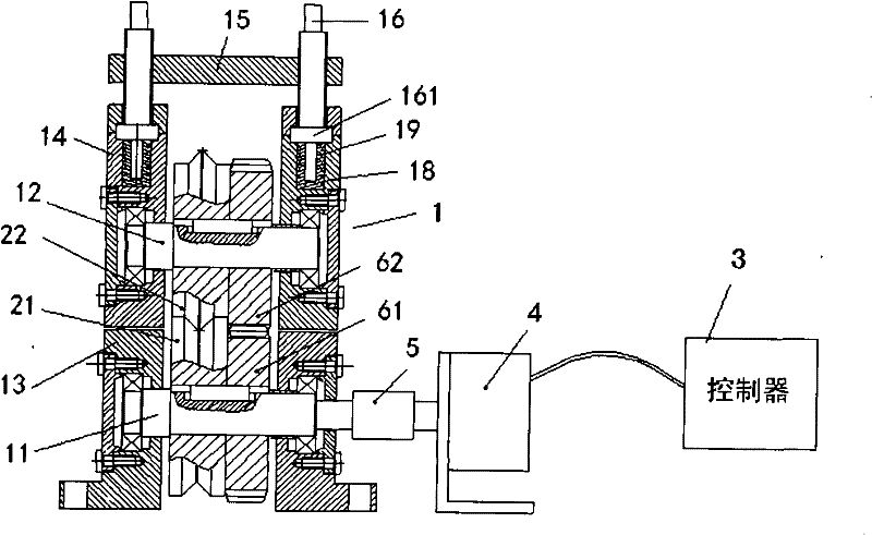
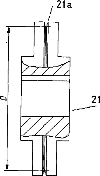
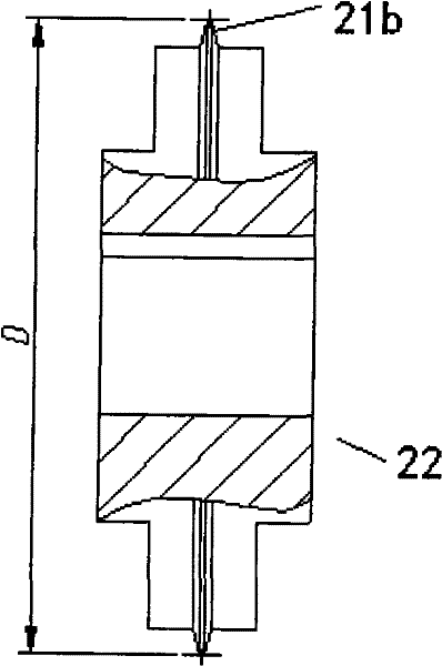
[0023] Such as figure 1 and figure 2 As shown, the fixed-length wire feeding device of the present invention includes a frame 1, a pair of wire feeding wheels, a controller 3, a motor 4, a shaft coupling 5 and a transmission mechanism.

[0024] The frame 1 includes a driving shaft 11 , a driven shaft 12 , a pair of driving shaft support seats 13 and a pair of driven shaft support seats 14 . The driving shaft 11 and the driven shaft 12 are arranged in parallel, the two ends of the driving shaft 11 are respectively supported on a pair of driving shaft supporting seats 13, and the two ends of the driven shaft 12 are respectively supported on a pair of driven shaft supporting seats 14. The driven shaft supporting seat 14 is arranged above the driving shaft supporting seat 13 .

[0025] The controller 3 is preferably a PLC controller, and the motor 4 is ...


PUM


Abstract

The invention discloses a fixed-length wire feeding device which comprises a stander, a pair of wire feeding wheels, a motor, a controller and a transmission mechanism, wherein the stander is provided with a driving shaft and a driven shaft; the pair of wire feeding wheels comprise a driving wheel sleeved on the driving shaft and a driven wheel sleeved on the driven shaft; the motor is used for driving the driving shaft to rotate; the controller is used for controlling the rotation angle of the motor; and the transmission mechanism is used for delivering power output by the motor to the driven wheel, so that the driven shaft and the driving shaft rotate synchronously at a constant speed. The invention also discloses a wire feeding method. In the method, the controller is utilized to control the rotation angle of the motor so as to control the rotation angles of the driven wheel and driving wheel which are used for feeding wires, thereby realizing the fixed-length wire feeding. According to the invention, the rotation angle of the motor is completely controlled by the controller, so that the fixed-length wire feeding can be realized; and in a wire feeding process, the position of the driven wheel can adaptively move up and down according to the diameter of a fuse wire under the action of a compensating spring, thereby eliminating the influence of the diameter error of the fuse wire on the wire feeding driving power and improving the wire feeding size precision.

Description

technical field [0001] The invention relates to a fixed-length wire feeding device and a wire feeding method thereof. Background technique [0002] As the technological content of electrical products is getting higher and higher, the development of wire threading machine has become one of the research difficulties in the field of electrical appliances at home and abroad. Especially in the process of producing fuses, wire threading is an important link in fuse assembly, due to its difficulty (0.25mm fuse passes through 0.35mm hole, unilateral allowable error is 0.05mm), efficiency requirements High (the system requires the wire feeding action of 80mm length to be completed within 0.5s) and high robustness requirements (the error of parts is more than ten times or even dozens of times the allowable error of threading), so efficient wire feeding It is also one of the problems to be solved urgently in the current fuse production field. At present, there is no self-developed wi...

Claims


Application Information

Patent Timeline
Patent Type & Authority Applications(China)
IPC IPC(8): B21F23/00
Inventor 何涛
Owner SHANGHAI UNIV OF ENG SCI
Learn More