Vibrating grate

A furnace grate and grate ring technology, applied in the field of slagging system in biomass gasification reaction chamber, can solve the problems of coking and ash that cannot be discharged smoothly and in time, manual slagging, etc.

Inactive Publication Date: 2012-01-25
张建超
View PDF3 Cites 0 Cited by
  • Summary
  • Abstract
  • Description
  • Claims
  • Application Information

AI Technical Summary

Problems solved by technology

[0003] In the existing gasification reaction chamber slagging system, once coking and large particles of ash appear, the entire gasification reaction chamber will be shut down and t

Method used


Image

  • Vibrating grate
  • Vibrating grate
  • Vibrating grate

Examples


Embodiment Construction

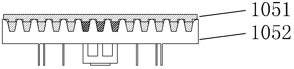
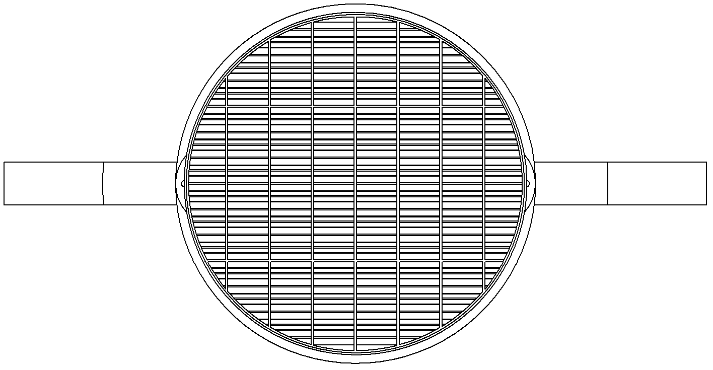
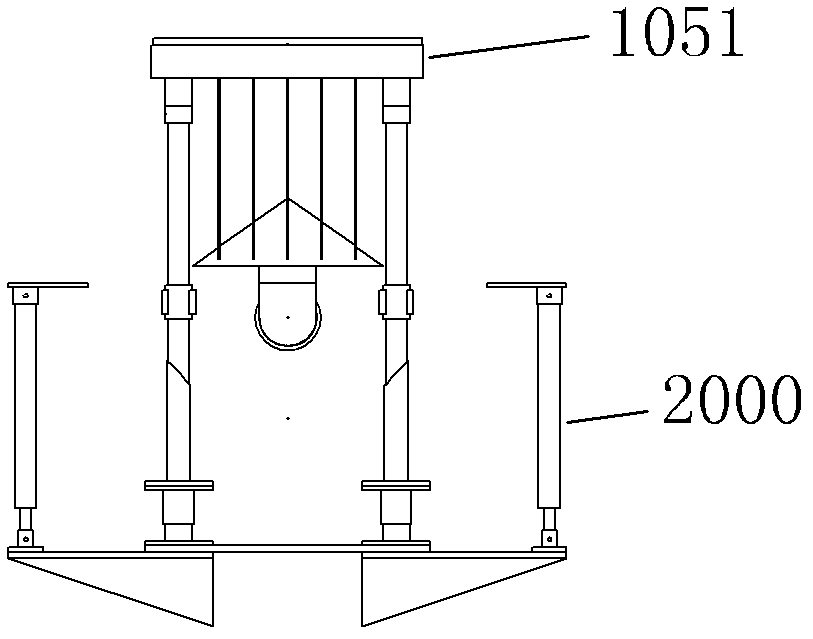
[0024] A vibrating grate 1, such as figure 1 As shown, it is made of high-temperature-resistant material and has a split structure of upper and lower layers; the lower grate 1052 is a fixed furnace composed of multiple trapezoidal stainless steel racks placed in a positive ladder shape and fixedly connected to the inner side of the grate ring through its two ends Castor, such as figure 2 As shown, it is fixed on the refractory material wall at the lower end of the gasification reaction chamber; the upper grate 1051 is a movable grate composed of multiple ladder-shaped stainless steel racks placed in an inverted ladder shape and fixedly connected to the inner side of the grate ring through its two ends ,Such as figure 2 As shown, it is connected and linked with the hydraulic cylinder 2000, such as image 3 As shown; the rack of the lower grate 1052 and the rack of the upper grate 1051 are correspondingly engaged, and the transverse gap at the joint is set according to the s...


PUM


Abstract

The invention relates to a vibrating grate which is in a split structure with an upper layer and a lower layer; the grate at the lower layer is a fixed grate, is placed in a regular trapezoid by a plurality of trapezoidal stainless steel racks and is formed by fixedly connecting two ends of the fixed grate to the inner side of a grate loop; the grate at the upper layer is a movable grate, is placed in an inverted trapezoid by a plurality of trapezoidal stainless steel racks, is formed by fixedly connecting two ends of the movable grate to the inner side of a grate loop, and is connected and linked with a hydraulic power device; the racks of the grate at the lower layer are correspondingly occluded with the racks of the grate at the upper layer, and the transverse gap between the racks of the grates at the upper layer and the lower layer which are adjacent at an occlusion part is set to be 5-80mm; and the hydraulic power device is controlled by a PLC (Programmable Logic Controller) automatic control system to drive the grate at the upper layer to vibrate at the frequency of not larger than 200 times/minute. In the invention, coked clinker shale particles are discharged through vibration and extrusion, thus the aims of continuous gasification and power generation are achieved, and the vibrating grate is applicable to a continuous gasification and power generation technology in the biomass gasification reaction process.

Description

technical field [0001] The invention relates to a slagging system for a biomass gasification reaction chamber. Background technique [0002] Biomass gasification power generation has always been an important key issue in the field of biomass energy for human beings, and continuous operation of equipment and slag discharge have become an important step. Hours of uninterrupted operation, while timely discharge of ash, in order to achieve the purpose of continuous power generation and energy consumption. [0003] In the existing gasification reaction chamber slagging system, once coking and large particles of ash appear, the entire gasification reaction chamber will be shut down and the entire set of biomass gasification equipment will stop running; the coking and ash generated cannot be discharged smoothly and in time , and even manual slag removal is required. Contents of the invention [0004] In view of the above-mentioned problems in the prior art, the present inventio...

Claims


Application Information

Patent Timeline
IPC IPC(8): C10J3/34
Inventor 张建超张瑜姜晨旭唐旻张建国
Owner 张建超
Why Eureka
Try Eureka