Vibrationless fluidized bed drying machine

A vibrating fluidized bed and dryer technology, applied in dryers, drying solid materials, drying gas layout, etc., can solve the problems of difficulty in controlling the discharge speed, sticking to the bed surface, high noise, etc., and reduce ventilation. Pipes and elbows, avoid dead beds, improve the effect of the life of the whole machine

Active Publication Date: 2013-08-21
山东宾利环保科技有限公司
View PDF8 Cites 0 Cited by
  • Summary
  • Abstract
  • Description
  • Claims
  • Application Information

AI Technical Summary

Problems solved by technology

[0004] 1. The vibration device must be installed, the noise is large, the bed is easy to vibrate and crack, the material moves unevenly, and the discharge speed is difficult to control. A vibration damping device needs to be designed between the box and the base
[0005] 2. The external blower device consumes a lot of energy
[0007] 4. The hot air flows unevenly in the box, and the wind cannot be evenly discharged from the air distribution plate, so that the material cannot be fully boiled, and the dead bed phenomenon is prone to occur, that is to say, under a certain wind pressure, if there is too much material added or added The material has a certain degree of adhesion, and it is easy for the material to fail to be blown by the wind or stick to the bed surface (wind distribution board). This phenomenon is called dead bed
If there is a dead bed, it is necessary to manually rake the material for drying, especially when the dead bed often occurs during commissioning, it is difficult to enter normal production

Method used


Image

  • Vibrationless fluidized bed drying machine
  • Vibrationless fluidized bed drying machine

Examples


Embodiment Construction

[0020] Embodiments of the present invention will be further described below in conjunction with accompanying drawings:

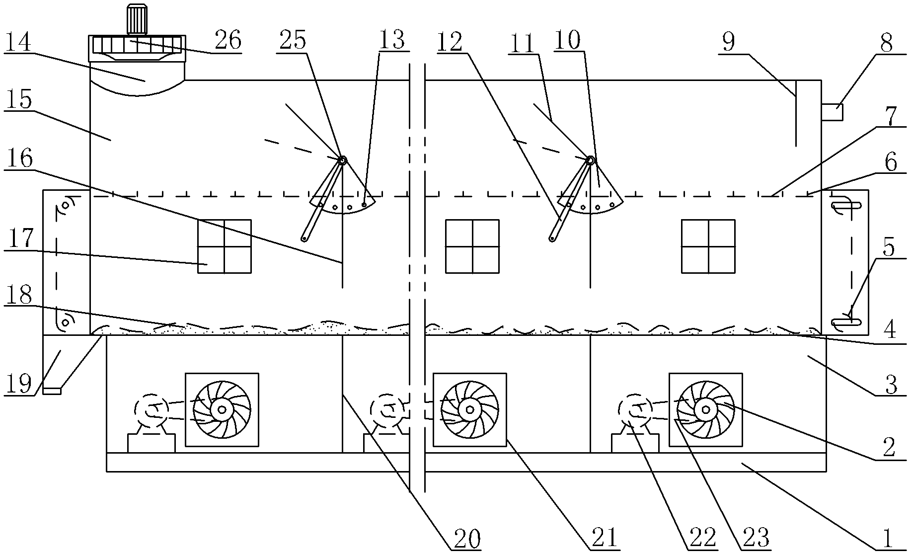
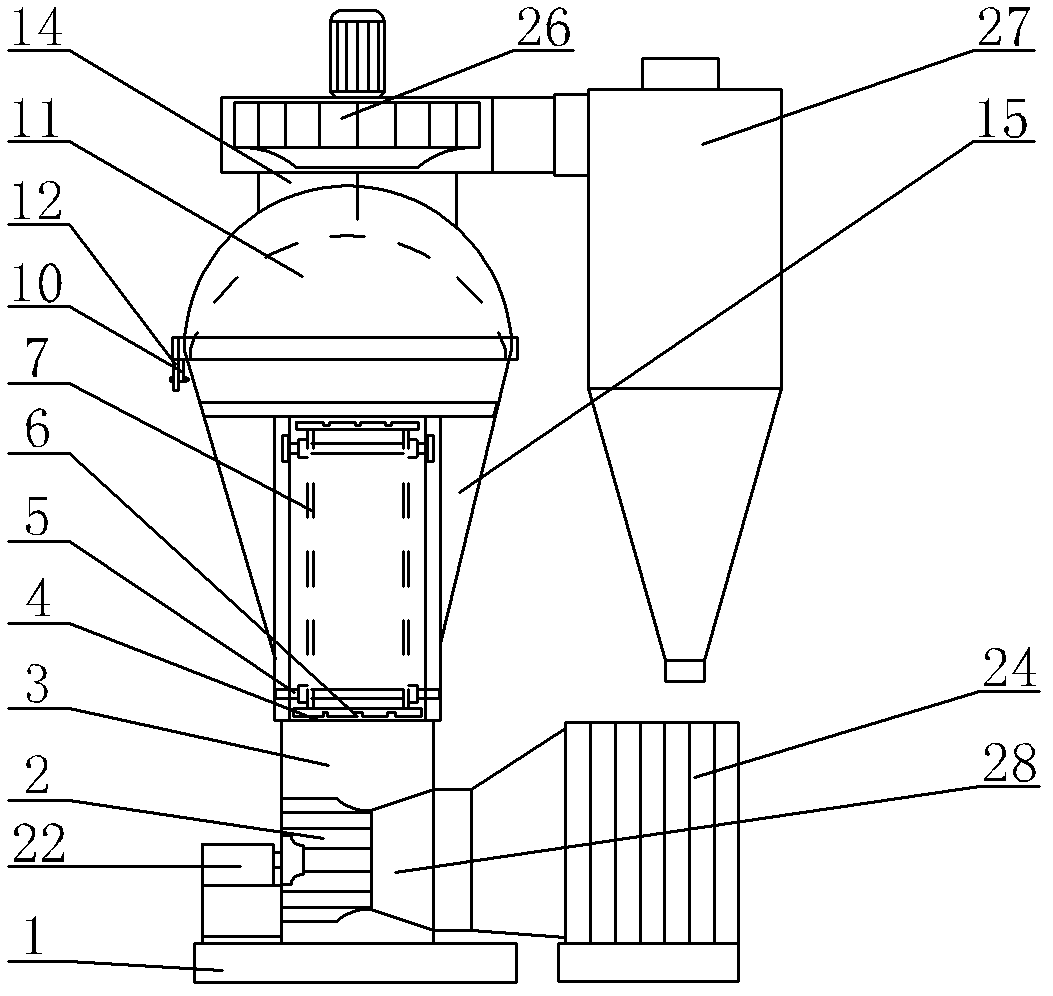
[0021] like figure 1 , 2 As shown, the non-vibration fluidized bed dryer of the present invention includes a base 1, a box body, a heat exchanger 24, an induced draft fan 26 and a dust collector 27, the box body is installed on the base 1, and the air outlet 14 of the box body Connect the induced draft fan 26, the induced draft fan 26 is connected to the dust collector 27, the air distribution plate 4 is arranged in the box and is divided into the upper box body 15 and the lower box body 3 by the air distribution plate 4, and the lower partition plate 20 is set in the lower box body 3, The lower partition 20 divides the lower casing 3 into a plurality of air chambers, and the corresponding lower partition 20 is provided with an upper partition 16 in the upper casing 15, and a blower device is arranged between two adjacent lower partitions 20 to blow air. T...


PUM


Abstract

The invention relates to a vibrationless fluidized bed drying machine, which belongs to the field of mechanical equipment and comprises a base, a box body, a heat exchanger, a draught fan and a deduster, wherein the box body is arranged on the base, an air outlet of the box body is connected with the draught fan, the draught fan is connected with the deduster, an air distribution plate is arranged in the box body, the box body is partitioned into an upper box body and a lower box body by the air distribution plate, lower partition boards are arranged in the lower box body, the lower box body is partitioned into a plurality of air chambers by the lower partition boards, upper partition boards are arranged in the upper box body corresponding to the lower partition boards, the top of the upper box body is provided with an upper ventilation duct, a blast device is arranged between two adjacent lower partition boards, and the blast device is connected with the heat exchanger. A duct is divided into the upper ventilation duct and a lower ventilation duct by the upper partition boards of the upper box body, air quantity of the upper ventilation duct and the lower ventilation duct can be adjusted by an adjusting plate so as to achieve an uniform discharge effect; the blast device is arranged between the two adjacent lower partition boards in the lower box body, energy is saved, the air quantity can be respectively adjusted according to different moisture contents of materials to obtain qualified materials; and the original vibration device is replaced by a material poking device to avoid the phenomenon of bed blocking.

Description

technical field [0001] The invention relates to a non-vibration fluidized bed dryer, which belongs to the field of mechanical equipment. Background technique [0002] With the development of my country's industry, a large number of industrial products use dryers to achieve dehydration processes, and widely used dryers can be roughly divided into fluidized bed dryers, drum dryers, vacuum dryers, etc. The working principle of the fluidized bed dryer is to vibrate the whole bed body through the vibrator to realize the moving process of the material from the inlet to the outlet. The hot air for drying materials is sent to the heat exchanger through the blower and the ventilation duct, and then enters the fluidized bed box. The hot air generates a certain wind pressure in the box, passes through the air distribution plate installed on the box, and then heats the material, and at the same time, the water evaporated by the material is taken out of the box through the air duct, ent...

Claims


Application Information

Patent Timeline
Patent Type & Authority Patents(China)
IPC IPC(8): F26B3/08F26B21/00F26B25/00
Inventor 高庆山
Owner 山东宾利环保科技有限公司
Why Eureka
Try Eureka