This helps you quickly interpret patents by identifying the three key elements:
Problems solved by technology
Method used
Benefits of technology
Problems solved by technology
At the same time, if the distance between the adjacent LED elements is reduced, the length of the bonding wire straddling between the adjacent LED elements becomes shorter when the LED row is viewed from above.
Method used
Image
Click on the blue label to locate the original text in one second.
Reading with bidirectional positioning of images and text.
Examples
Embodiment approach 1
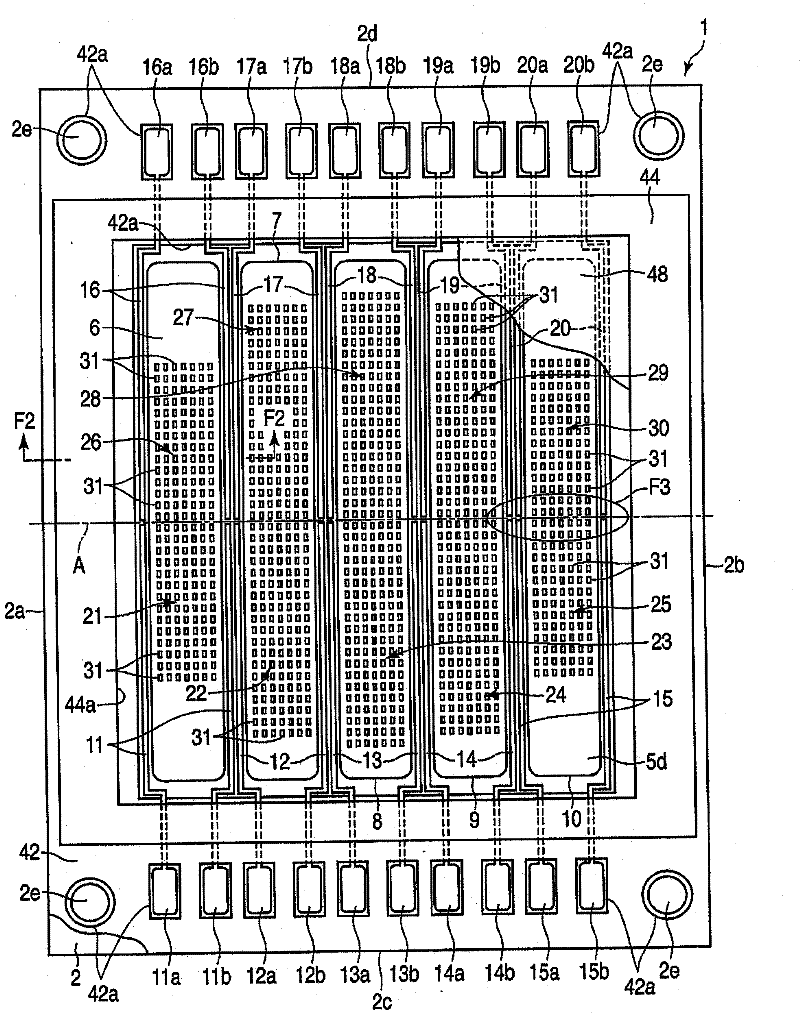
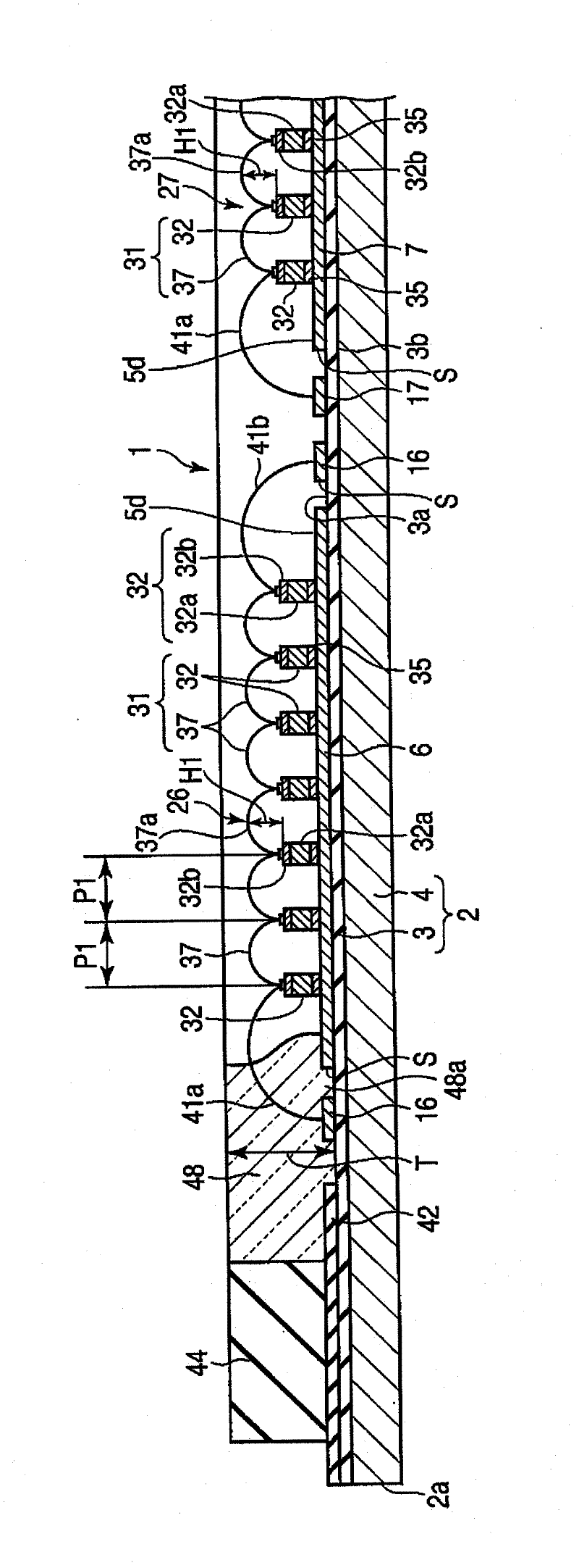
[0089] figure 1 and figure 2 A COB (chipon board: chip on board) type light emitting module 1 is shown. For example, the light emitting module 1 is arranged at the focal point of a projection lens group of a spotlight, and is used as a light source of the spotlight.
[0090] The light emitting module 1 includes a module substrate 2 serving as a base. Such as figure 1 As shown, the module substrate 2 has a rectangular shape having a pair of long sides 2a, 2b and a pair of short sides 2c, 2d. The long sides 2a, 2b are parallel to each other, and the short sides 2c, 2d are also parallel to each other. Also, the module substrate 2 has four corners. Mounting holes 2 e are formed at respective corners of the module substrate 2 .
[0091] Such as figure 2 As shown, the module substrate 2 includes a synthetic resin insulating layer 3 and a metal plate 4 . The insulating layer 3 includes a first face 3a and a second face 3b. The second surface 3b is located on the opposite ...
Embodiment approach 2
[0182] Embodiment 2 differs from Embodiment 1 above in matters related to die-bonding materials for bonding light-emitting diode elements to the first to fifth metal reflective layers. The basic structure of the light emitting module except for the die bonding material is the same as that of the first embodiment described above. Therefore, in the second embodiment, the same components as those in the first embodiment are given the same reference numerals, and descriptions thereof are omitted.
[0183] Such as Figure 9 and Figure 10 As shown, the die bonding material 35 is applied so as to cover the first to fifth metal reflective layers 6 to 10 and sandwiched between the silver layer 5 c and the substrate 32 a of each LED element 32 . The die-bonding material 35 covers the entire area except the side edges of the silver layer 5c.
[0184] In other words, the die bonding material 35 continuously covers the region corresponding to the plurality of LED elements 32 , the regi...
Embodiment approach 3
[0202] Embodiment 3 is different from the above-mentioned Embodiment 1 in matters related to die-bonding materials for bonding light-emitting diode elements to the first to fifth metal reflective layers. The basic structure of the light emitting module except for the die bonding material is the same as that of the first embodiment described above. Therefore, in Embodiment 3, the same components as those in Embodiment 1 are given the same reference numerals, and description thereof will be omitted.
[0203] Figure 11 is corresponding to the above-mentioned Embodiment 1 image 3 The diagram in FIG. 2 mainly shows the states of the fifth and tenth light emitting parts 25 and 30 adhered to the fifth metal reflective layer 10 .
[0204] Such as Figure 11As shown, the die bonding material 35 for bonding the LED elements 32 of the LED row 31 to the light reflective surface 5 d of the fifth metal reflective layer 10 has a plurality of pad portions 51 . The pad portion 51 corresp...
PUM
Abstract
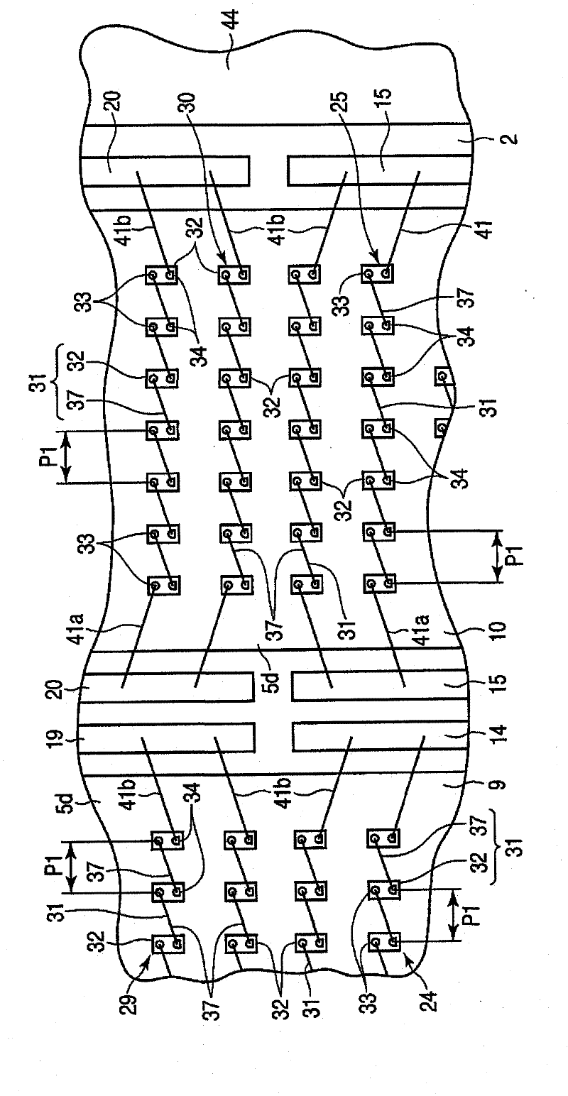
A light-emitting module (1) provided with a module board (2), light-emitting diode lines (31), and a sealing member (48). Each light-emitting diode line (31) includes a plurality of light-emitting diodes (32) and a plurality of bonding wires (37) connected between the light-emitting diodes (32). Each light-emitting diode (32) has a pair of electrodes (33, 34) and has a rectangular shape that extends to the direction that the electrodes (33, 34) are lined up in. The sealing member (48) is deposited on the module board (2) so as to seal the light-emitting diode lines (31). The light-emitting diodes (32) are arranged with clearance to each other in directions that intersect the direction in which the electrodes (33, 34) are lined up in, and are arranged so that the electrodes (33, 34) of the same polarity between adjacent light-emitting diodes (32) are adjacent in the arrangement direction of the light-emitting diodes (32). The bonding wires (37) are laid in a manner diagonal to the arrangement direction of the light-emitting diodes (32) so as to connect electrodes (33, 34) of different polarities of the adjacent light-emitting diodes (32).
Description
technical field [0001] The invention relates to a lighting module with a plurality of light-emitting diode elements. The invention also relates to a lighting device using a lighting module with a plurality of light-emitting diode elements as light source. Background technique [0002] For example, Patent Document 1 discloses a COB (chipon board: chipon board) type lighting device. This lighting device includes: a resin substrate having a white surface, a plurality of light emitting diode rows, a reflector, and a sealing member. [0003] The LED rows extend linearly along the surface of the resin substrate, and the LED rows are arranged in parallel with each other at intervals in a direction perpendicular to the direction in which the LED rows extend. The reflector is bonded to the surface of the resin substrate to surround the LED row. The sealing member is made of transparent silicone resin mixed with phosphor. The sealing member is filled in the area surrounded by th...
Claims
Application Information
Patent Timeline
Application Date:The date an application was filed.
Publication Date:The date a patent or application was officially published.
First Publication Date:The earliest publication date of a patent with the same application number.
Issue Date:Publication date of the patent grant document.
PCT Entry Date:The Entry date of PCT National Phase.
Estimated Expiry Date:The statutory expiry date of a patent right according to the Patent Law, and it is the longest term of protection that the patent right can achieve without the termination of the patent right due to other reasons(Term extension factor has been taken into account ).
Invalid Date:Actual expiry date is based on effective date or publication date of legal transaction data of invalid patent.

