
Piezoelectric ceramic drive type ultra-miniature air pump
A piezoelectric ceramic drive, piezoelectric ceramic technology, applied in the direction of pumps, machines/engines, liquid variable capacity machinery, etc., can solve the problem of affecting the fluid movement speed and speed transmission efficiency, reducing the performance of piezoelectric pumps, and unreasonable Structure and other issues, to achieve the effect of expanding the scope of work, preventing excessive current, and saving space
- Summary
- Abstract
- Description
- Claims
- Application Information
AI Technical Summary
Problems solved by technology
Method used
Image

Examples
Embodiment 1
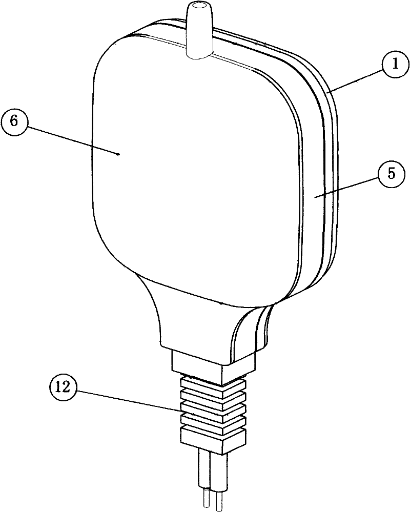
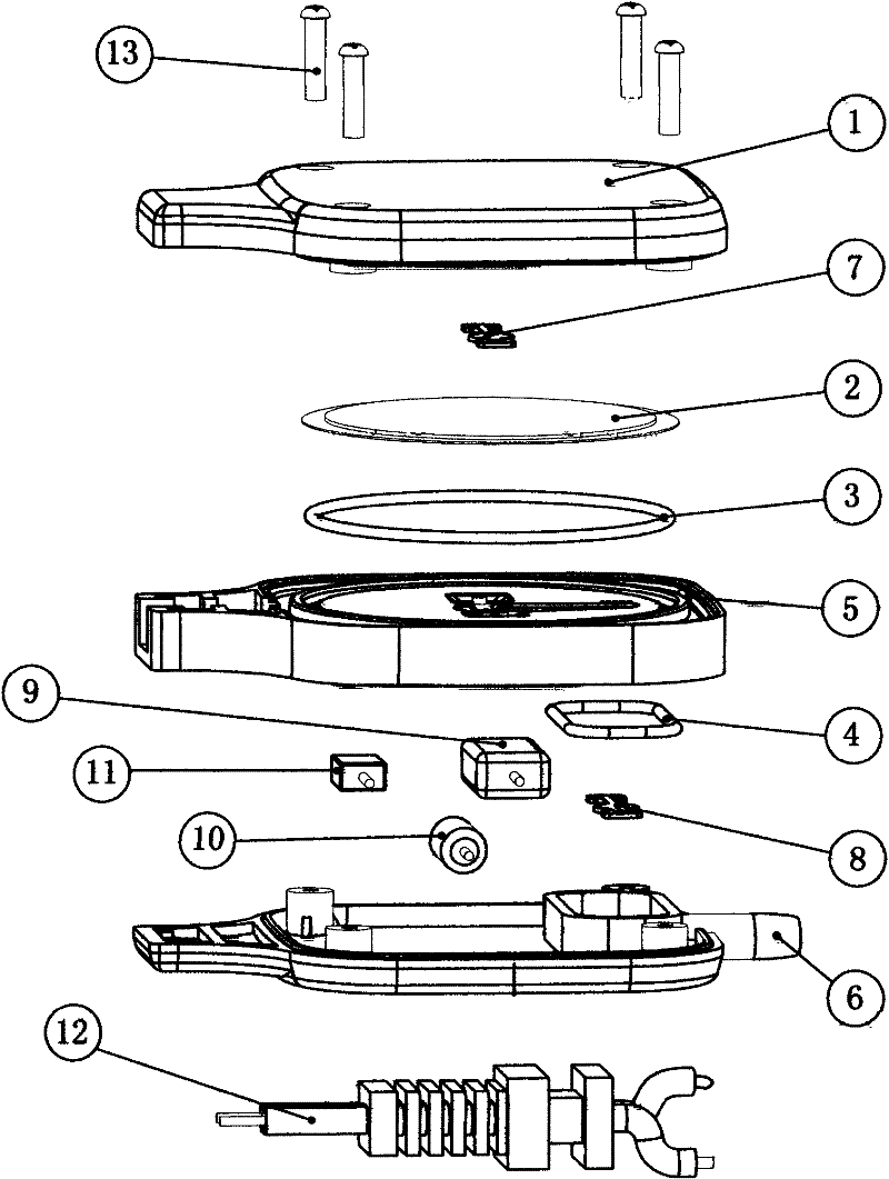
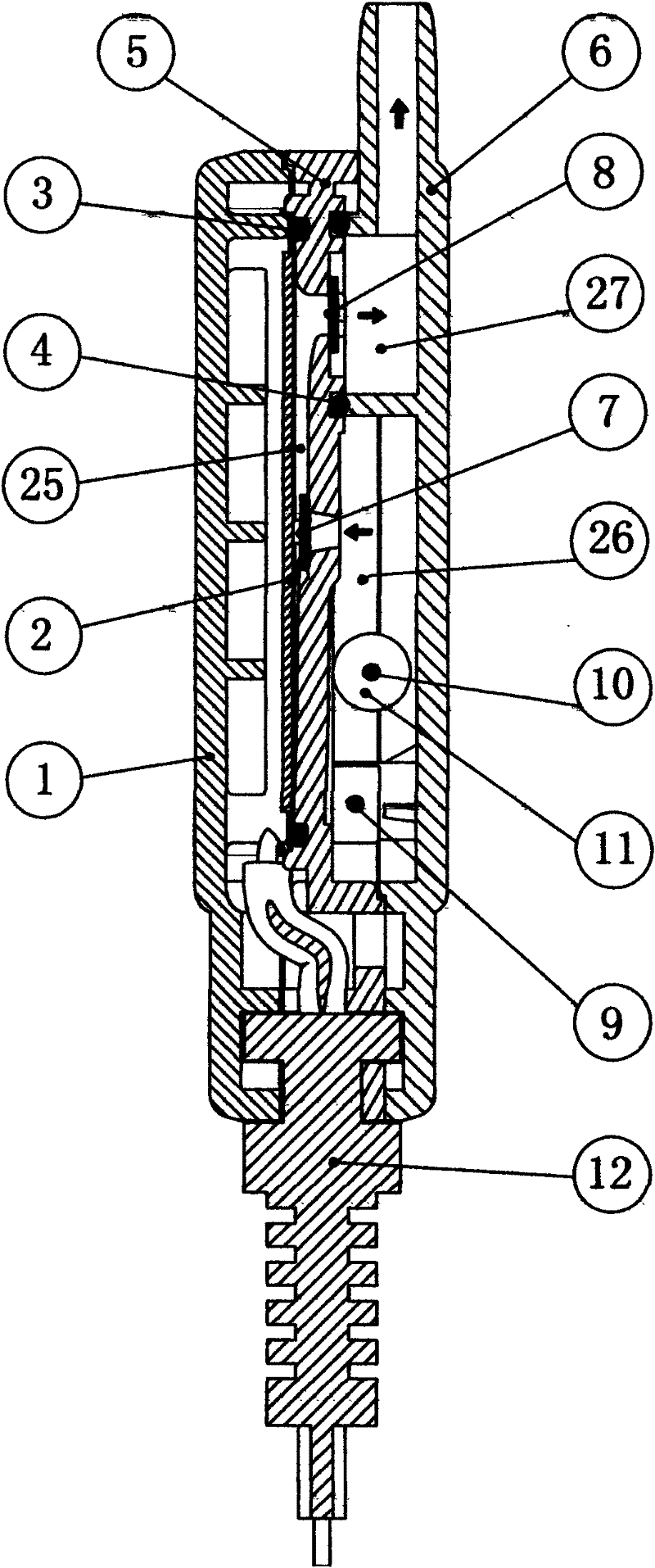
[0060] Embodiment 1, see Figure 1-Figure 3 . The pump body of this embodiment has a pump lower cover 1, a pump base 5 and a pump upper cover 6, and a piezoelectric ceramic transducer plate 2 is housed in the cavity formed after the pump base 5 and the pump lower cover 1 are assembled; The air inlet and exhaust port of 5 are respectively equipped with an air intake valve 7 and an exhaust valve 8, wherein the air intake valve 7 corresponds to the center of the maximum swing range of the piezoelectric ceramic transducer plate 2, and the air intake valve 7 takes in air The cavity at the entrance is the air intake chamber 26 in the pump upper cover 6, which communicates with the assembly gap of the pump body; an o-shaped sealing ring A3 is installed between the piezoelectric ceramic transducer plate 2 and the pump seat 5, and the The back of the pump base 5 ( image 3 On the right side of the pump seat 5) and the pump upper cover 6, an o-ring B4 is installed. The pump upper cov...
Embodiment 2
[0066] Example 2, see Figure 4-Figure 6 . In this embodiment, only the part connected to the commercial power is changed to a plug structure, replacing the power cord 12 in Embodiment 1. The power plug 14 is molded and fixed on the pump base 5 . One of the inserts is welded to the capacitor 9 through a wire, and the other insert is welded to the metal substrate 21 of the piezoelectric ceramic transducer 2 through a lead. Wiring reference Figure 12 , except that the power supply cord 12 is replaced with the power plug 14 (only this specific structure is different), other structures are the same as the pump in embodiment 1. The advantage of adopting the structure of the power plug 14 is that the use of raw materials can be saved, the space used can be saved, and the whole pump looks simpler and clearer. Working principle is the same as embodiment 1.
Embodiment 3
[0067] Example 3, see Figure 7-Figure 9 . This embodiment is a single piezoelectric ceramic transducer plate 2 double-chamber air pump 25 structure, including the pump lower cover 1 and the pump base 5, after the pump base 5, the pump lower cover 1 and the end exhaust connector 18 are assembled to form a sealed In the cavity, a piezoelectric ceramic transducer 2 is installed between the pump base 5 and the pump lower cover 1, forming a sealed and independent working pump chamber 25 on both sides of the piezoelectric ceramic transducer 2, the pump lower cover 1 and the pump base 5 are equipped with intake valve 7, o-ring A3 and o-ring B4 respectively; an exhaust connector 18 is installed at the air outlet of the upper end surface of the pump lower cover 1 and the pump seat 5, and its function is to connect the two The gases in the pump chambers 25 are brought together; two exhaust valves 8 and o-rings C19 are installed on the exhaust connector 18. The pump lower cover 1 and ...
PUM
| Property | Measurement | Unit |
|---|---|---|
| Thickness | aaaaa | aaaaa |
| Withstand voltage | aaaaa | aaaaa |
| Capacitance | aaaaa | aaaaa |
Abstract
Description
Claims
Application Information