Driving method of image display device

A technology of image display device and driving method, applied in the direction of static indicators, instruments, etc.

Active Publication Date: 2015-04-29
JAPAN DISPLAY INC
View PDF12 Cites 0 Cited by
  • Summary
  • Abstract
  • Description
  • Claims
  • Application Information

AI Technical Summary

Problems solved by technology

Specifically, for example, with the development of color liquid crystal display devices, along with increased fineness, a larger color reproduction range, and increased luminance, the power consumption of backlights has also increased.

Method used


Image

  • Driving method of image display device
  • Driving method of image display device
  • Driving method of image display device

Examples


no. 1 example

[0242]The first embodiment relates to an image display device driving method according to the first mode, the sixth mode, the eleventh mode, the sixteenth mode, and the twenty-first mode of the present disclosure, and the first mode, the sixth mode, the The image display device component driving methods of the eleventh mode, the sixteenth mode and the twenty-first mode.

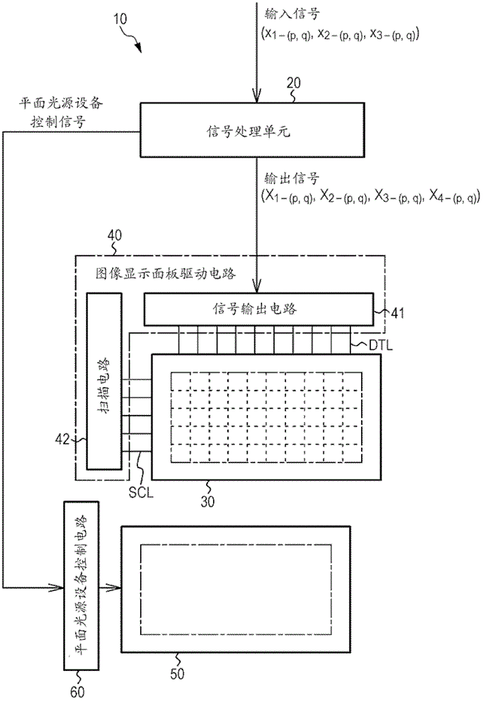
[0243] Such as figure 2 As shown in the conceptual diagram in , the image display device 10 according to the first embodiment includes an image display panel 30 and a signal processing unit 20 . Also, the image display device assembly according to the first embodiment includes the image display device 10 and the planar light source device 50 that illuminates the image display device (specifically, the image display panel 30 ) from behind. Now, if Figure 3A and 3B As shown in the conceptual diagram in , the image display panel is configured with P 0 ×Q 0 pixels (horizontal direction P 0 pixels, vertica...

no. 2 example

[0367] The second embodiment is a modification of the first embodiment. As the planar light source device, a direct type planar light source device according to the related art can be used, but for the second embodiment, a planar light source device 150 of a divided driving method (partial driving method) to be described below is used. Note that the extension processing itself should be the same as that described in the first embodiment.

[0368] Figure 9 A conceptual diagram showing an image display panel and a planar light source device constituting an image display device assembly according to a second embodiment, Figure 10 shows a circuit diagram of a planar light source device control circuit according to a planar light source device constituting an image display device assembly, and Figure 11 , schematically shows the layout and array state of the planar light source units and the like according to the planar light source device constituting the image display device...

no. 3 example

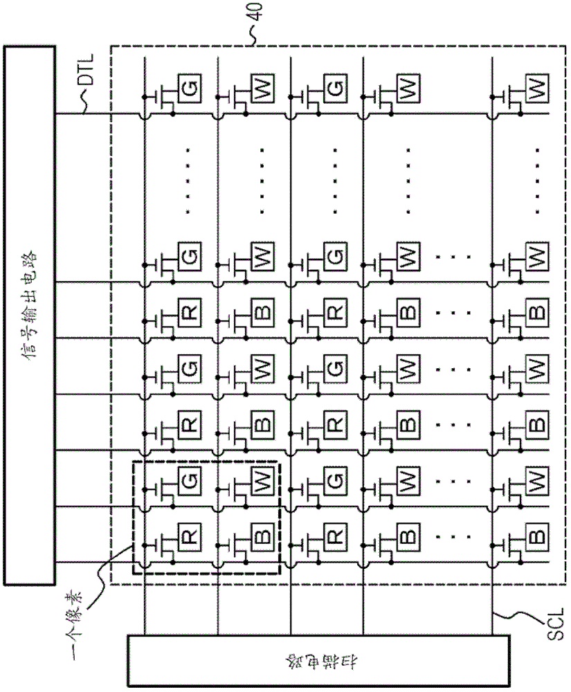
[0404] The third embodiment is also a modification of the first embodiment. exist Figure 13 An equivalent circuit diagram of the image display device according to the third embodiment is shown in , and in Figure 14 A conceptual diagram of an image display panel constituting an image display device is shown in . As for the third embodiment, an image display device to be described below is used. Specifically, the image display device according to the third embodiment includes an image display panel composed of light emitting units UN for displaying color images, the light emitting units UN are arranged in a two-dimensional matrix shape, each light emitting unit UN is composed of The first light-emitting device (corresponding to the first sub-pixel R), the second light-emitting device for emitting green (corresponding to the second sub-pixel G), the third light-emitting device for emitting blue (corresponding to the third sub-pixel B), and a fourth light-emitting device (cor...


PUM


Abstract

An image display device includes an image display panel configured of pixels made up of first, second, third, and fourth sub-pixels being arrayed in a two-dimensional matrix shape, and a signal processing unit into which an input signal is input and from which an output signal based on an extension coefficient is output, and causes the signal processing unit to obtain a maximum value of luminosity with saturation S in the HSV color space enlarged by adding a fourth color, as a variable, and to obtain a reference extension coefficient based on the maximum value, and further to determine an extension coefficient at each pixel from the reference extension coefficient, an input signal correction coefficient based on the sub-pixel input signal values at each pixel, and an external light intensity correction coefficient based on external light intensity.

Description

technical field [0001] The present disclosure relates to a driving method of an image display device. Background technique [0002] In recent years, for example, with the development of image display devices such as color liquid crystal display devices and the like, an increase in power consumption accompanying their high performance has become a problem. Specifically, for example, with the development of color liquid crystal display devices, power consumption of backlights has also increased along with increased fineness, larger color reproduction range, and increased luminance. In order to solve this problem, a technique has attracted attention in which, in addition to three sub-pixels of a red display sub-pixel for displaying red, a green display sub-pixel for displaying green, and a blue display sub-pixel for displaying blue, For example, a white display sub-pixel for displaying white is added to form a four-sub-pixel configuration, so that brightness can be improved th...

Claims


Application Information

Patent Timeline
Patent Type & Authority Patents(China)
IPC IPC(8): G09G3/32G09G3/34
CPCG09G3/3426G09G3/3648G09G2320/0646G09G2360/145G09G2340/06G09G2300/0452G09G3/3413
Inventor 东周长妻敏之境川亮加边正章
Owner JAPAN DISPLAY INC
Why Eureka
Try Eureka