Directive thermosyphon-type heat conducting column

A thermosyphon and directional technology, which is applied in semiconductor devices, cooling/ventilation/heating transformation, semiconductor/solid-state device components, etc., can solve problems such as inability to achieve circulation and heat dissipation effects that cannot reach the best state

Inactive Publication Date: 2012-02-01
姚明辉
View PDF5 Cites 13 Cited by
  • Summary
  • Abstract
  • Description
  • Claims
  • Application Information

AI Technical Summary

Problems solved by technology

[0003] Although the above-mentioned thermal conduction column 90 can achieve the circulating heat dissipation effect of liquid vapor phase, cooling and liquefaction due to natural phenomena such as gravity / capillary siphon by virtue of the crystallization or sintered block or copper mesh on the inner wall of the column body 91, the column body 91 There is no proper space partition setting in the interior, so that the rising airflow after the liquid vapor phase falls after encountering the top cover 92, but the descending vapor flow will be opposed to the subsequent rising airflow, and the overall smooth circulation cannot be achieved. As a result, its heat dissipation effect cannot reach the best state, and it is obviously not an ideal composition design. It is necessary to further improve and solve the problem.

Method used


Image

  • Directive thermosyphon-type heat conducting column
  • Directive thermosyphon-type heat conducting column
  • Directive thermosyphon-type heat conducting column

Examples


Embodiment Construction

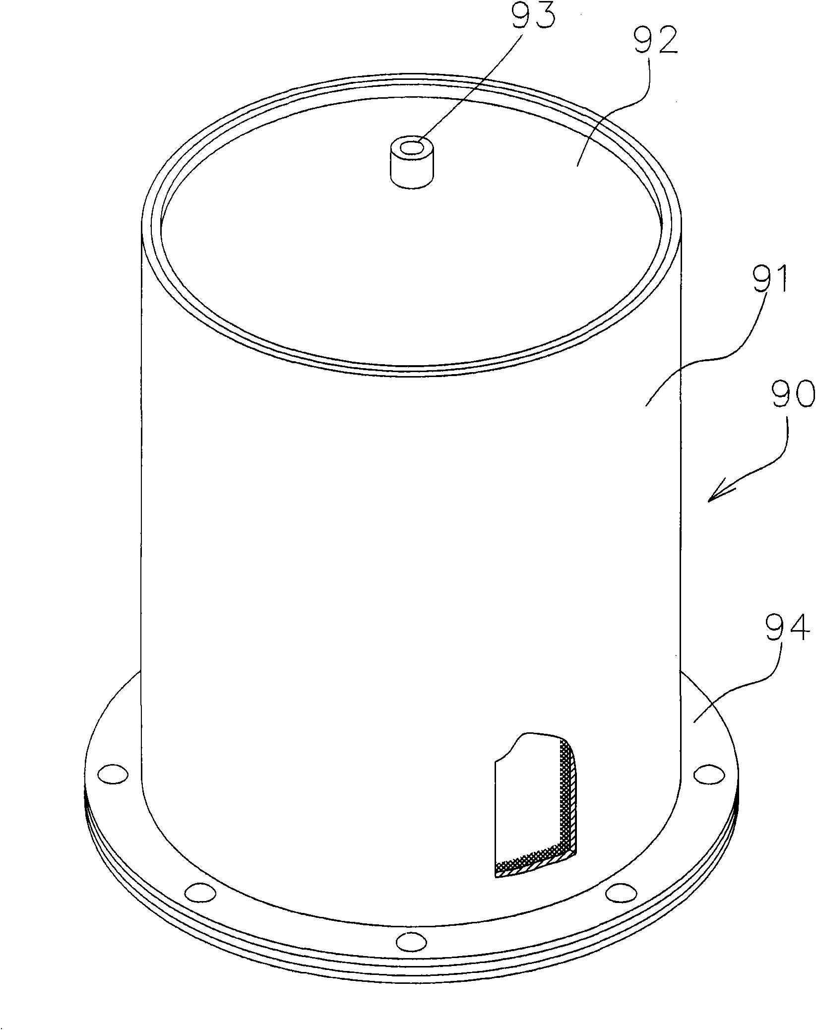
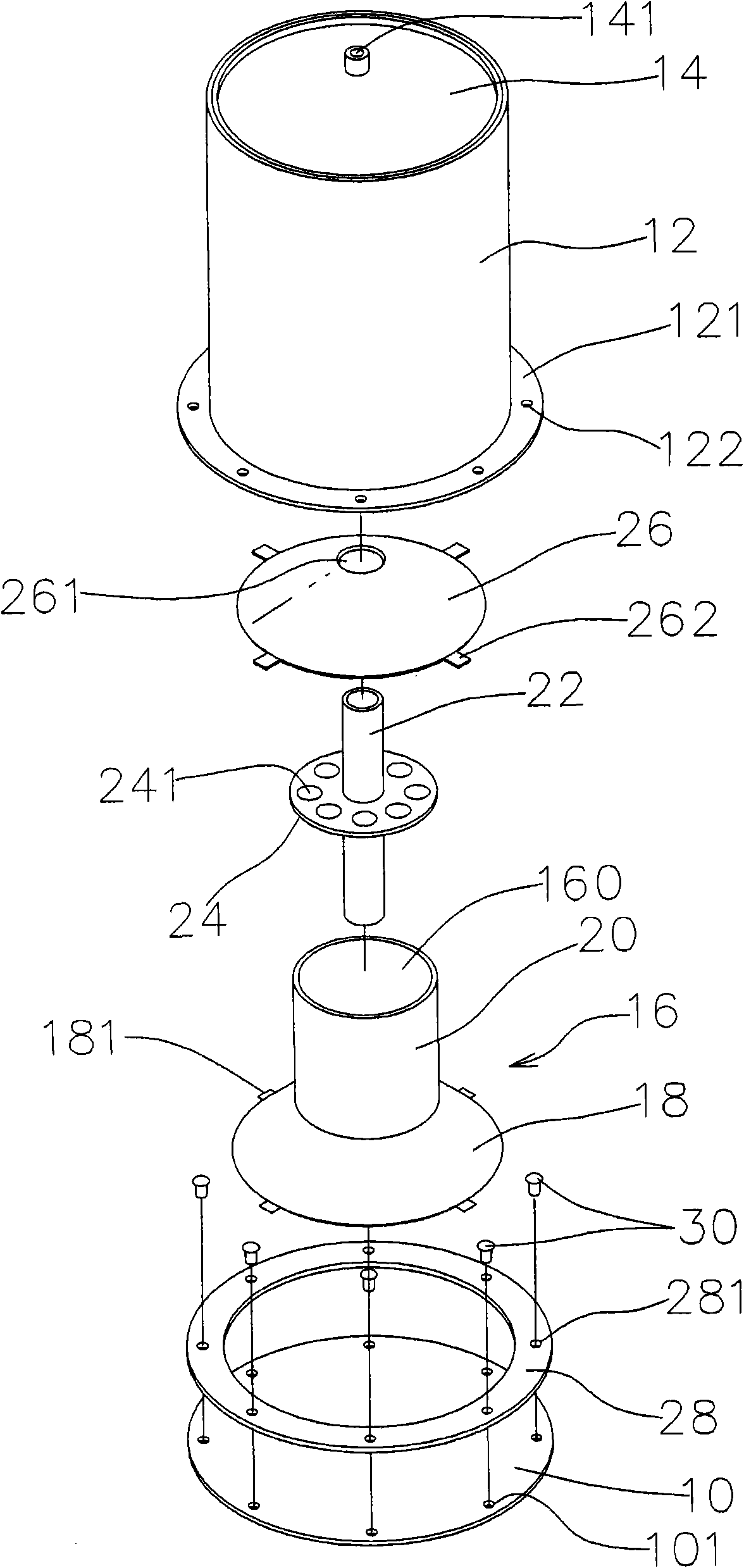
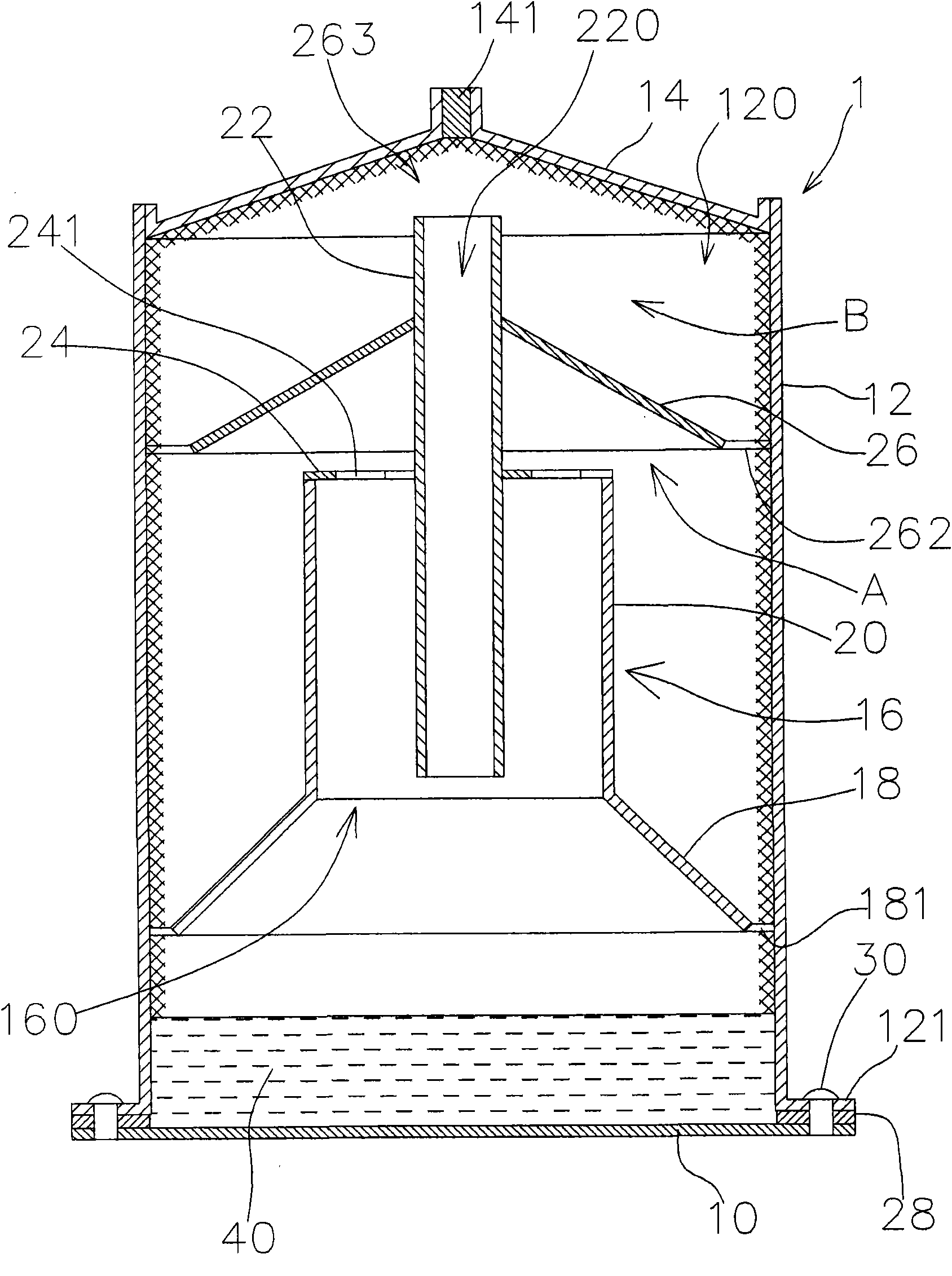
[0029] see figure 2 , image 3 , which is a schematic diagram of the first preferred embodiment of the directional thermosiphon heat conduction column of the present invention, which includes a heat conduction column 1, and the heat conduction column 1 further includes a cylinder 12, a guide 16 and a partition 26. The column 12 is a hollow cavity, that is, the column 12 has an action space 120 inside, and the inner wall surface of the column 12 is provided with metal crystals, metal powder sintered blocks or copper mesh on the inner wall surface of the action space 120 or capillary structures such as grooved pipes or mesh pipes, the bottom end of the cylinder 12 is provided with a protruding end edge 121 (the upper and lower directions or the front and rear directions referred to in the present invention are according to the orientation of the figure. For example, the application is not limited to the vertical setting), the upper ring of the connecting edge 121 is provided w...


PUM


Abstract

The invention discloses a directive thermosyphon-type heat conducting column, which comprises a column body and at least one separating piece, wherein the column body, a top cover and a base form a closed hollow chamber and liquid is contained in the column body; the separating piece is positioned in the column body and consists of a mask which tilts towards the base, at least one first channel is formed on one side of the separating piece relative to the direction of the base and at least one second channel is formed on one side of the separating piece relative to the direction of the top cover. Therefore, the situations that hedging occurs during the liquid/vapor change of the liquid in the heat conducting column and further the efficiency of heat dissipation circulation is affected can be avoided.

Description

technical field [0001] The invention relates to a heat dissipation structure, in particular to a heat conduction column with smooth and good heat conduction effect and excellent heat conduction effect. Background technique [0002] The existing computer, electronics, optoelectronics and other industries are changing with each passing day. As far as computers are concerned, the improvement of the performance of the central processing unit (CPU) is often accompanied by the generation of greater heat. Therefore, it is necessary to design and adopt more effective heat dissipation technology. Solve the problem of heat dissipation; another example is the development and application of light-emitting diodes (LightEmitting Diodes, LED) is an important project in today's lighting industry, and the life and function of light-emitting diodes (LEDs) are related to the quality of its heat dissipation measures, which is also the current development and application of LED key issues above....

Claims


Application Information

Patent Timeline
Patent Type & Authority Applications(China)
IPC IPC(8): H01L23/427H05K7/20
Inventor 姚明辉
Owner 姚明辉
Why Eureka
Try Eureka