Tooth implantation guide tool set and tooth implantation guide sleeve thereof

A technology of guiding tools and guiding sleeves, which is applied in the field of dental implant tool sets and components, which can solve the problems of increased tool manufacturing costs, increased working distance, and increased working space required for dental implants, so as to ensure the effect of lubrication and cooling, The effect of stable and safe use and shortened application space

Pending Publication Date: 2021-01-29
JOY INT CO
View PDF4 Cites 0 Cited by
  • Summary
  • Abstract
  • Description
  • Claims
  • Application Information

AI Technical Summary

Problems solved by technology

[0005] However, the implementation of the previously disclosed special cutter 300 has the following problems. The installation of the convex diameter portion 302 on the special cutter 300 will greatly increase the manufacturing cost of the cutter. In addition, when a dentist uses a cutter set, he must prepare a set of traditional cutters. Purchase an additional set of special knife sets, resulting in an increase in medical costs
Although the design of the special knife 300 and the knife guide hole 201 can stabilize the working direction of the special knife 300, this design has the problem of greatly increasing the working space required for dental implants, especially resulting in the overall The working distance increases. When the implant site is close to the back row of teeth, it is difficult to carry out the guided implant operation due to the insufficient opening distance of the upper and lower jaws of the human body. Therefore, it often happens that the back row of teeth cannot be guided. type implant, but need to be replaced by a general cutter 102 (such as figure 1 Shown) Problems with traditional implants
[0006] The use of the special tool 300 also has the following pro

Method used


Image

  • Tooth implantation guide tool set and tooth implantation guide sleeve thereof
  • Tooth implantation guide tool set and tooth implantation guide sleeve thereof
  • Tooth implantation guide tool set and tooth implantation guide sleeve thereof

Examples


Embodiment Construction

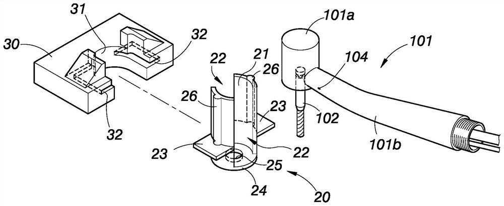
[0033] see image 3 , Figure 4 ,and Figure 5 As shown, it is the first embodiment of the present invention, and the dental implant guiding tool set includes a handpiece 101 , a dental implant guiding sleeve 20 and a dental mold fixing element 30 .

[0034] The mobile phone 101 has a head 101a for replacing the cutter 102 and providing power for the cutter 102, and a connecting handle 101b connected to the head of the cutter 101a.

[0035] The implant guide sleeve 20 has a machine head guide hole 21 arranged axially corresponding to the shape of the machine head 101a, and at least one side opening 22 on the side of the machine head guide hole 21 corresponding to the connecting handle 101b , two positioning pieces 23 radially arranged on the periphery of both sides of the implant guide sleeve 20 and a limiting plate 24 located at the bottom of the guide hole 21 of the machine head, the center of the limiting plate 24 is provided with a cutter perforation 25, The outer edge ...


PUM


Abstract

The invention mainly provides a tooth implantation guide tool set and a tooth implantation guide sleeve thereof. The tooth implantation guide tool set comprises a handpiece, the tooth implantation guide sleeve and a tooth mold fixing element, wherein the tooth implantation guide sleeve is provided with a handpiece head guide hole which is axially arranged and corresponds to the shape of a handpiece head of the handpiece, and at least one lateral opening which is positioned on the side surface of the handpiece head guide hole and corresponds to a connecting handle of the handpiece. Therefore, the tooth implantation guide sleeve can directly guide the handpiece head of the handpiece to avoid direct contact between the tooth implantation guide sleeve and a cutter mounted on the handpiece, anda special cutter with a special guide design is not needed, so a traditional cutter can be directly used for guide type tooth implantation operation to reduce operation cost, the minimum constructionspace of the whole tooth implantation guide tool set can be shortened, and the effects of being more convenient, safer and more comfortable are achieved.

Description

technical field [0001] The invention relates to instruments and equipment used by dentists, in particular to a tool set and its components applied to dental implants. Background technique [0002] Dental implant is a dental restoration technology that implants implants (artificial tooth roots) into the alveolar bone of the human body and then installs dentures to make up for missing teeth. One of the key devices that affects the effect of dental implants during the process is the mobile phone (handpiece) The aforementioned mobile phone can also be called a dental handpiece (Dental handpiece). [0003] like figure 1 Shown is a schematic diagram of the existing dental implant means. Before the implant is installed, a hole must be drilled or reamed and ground on the alveolar bone 100 to facilitate subsequent implant implantation operations. The traditional drilling method, After first installing a suitable cutter 102 on the mobile phone 101, the alveolar bone 100 is directly ...

Claims


Application Information

Patent Timeline
IPC IPC(8): A61C1/08A61C8/00
CPCA61C1/082A61C1/084A61C8/0089
Inventor 李秉成
Owner JOY INT CO
Why Eureka
Try Eureka