Socket joint type silicon core lapping structure and method capable of increasing contact area and reducing electric resistance

A contact area, plug-in technology, applied in chemical instruments and methods, silicon compounds, inorganic chemistry, etc., can solve the problems of transverse silicon core spherical cracks, increased processing costs, scrapped high-frequency coils, etc., to ensure electrical conductivity. , The effect of improving the firmness and reducing the processing steps

Active Publication Date: 2012-02-08
LUOYANG JINNUO MECHANICAL ENG
View PDF5 Cites 8 Cited by
  • Summary
  • Abstract
  • Description
  • Claims
  • Application Information

AI Technical Summary

Problems solved by technology

[0003] The Chinese patent that was first applied for: discloses a hole-type silicon core lapping method that can effectively increase the contact area and reduce resistance. This patent proposes a lapping method for spherical silicon cores. Silicon core spheres are arranged at both ends of the core, and jacks are respectively set at the lower part of the two silicon core spheres, and the plugs at the upper end of the vertical silicon core are matched with the jacks to form a connection method that increases the contact area and reduces resistance. However, in practical applications, it is found that when drilling holes on the horizontal silicon core sphere, it will often cause the horizontal silicon core sphere to crack, or even break, and the yield is relatively low, which increases the processing cost; End-drawing a sphere is also a relatively complex and costly process. This process is not only complicated, but also when drawing a horizontal silicon core sphere, if you are not careful, the high-frequency coil will contact the silicon core and cause ignition. The occurrence of the phenomenon may even cause the high-frequency coil to be scrapped, and affect the progress of the process. The drawing process must be stopped, and the next drawing process will be carried out by replacing the high-frequency coil. Among them, when the equipment is turned on again during the shutdown, it is necessary to prevent raw materials from The rod is oxidized during the drawing process, and the seed crystal must be replaced with a new one. At the same time, the silicon core furnace must be vacuumed, flushed with protective gas, and heated.

Method used


Image

  • Socket joint type silicon core lapping structure and method capable of increasing contact area and reducing electric resistance
  • Socket joint type silicon core lapping structure and method capable of increasing contact area and reducing electric resistance
  • Socket joint type silicon core lapping structure and method capable of increasing contact area and reducing electric resistance

Examples


Embodiment Construction

[0040] The present invention can be explained in more detail with reference to the following examples, but the present invention is not limited to these examples.

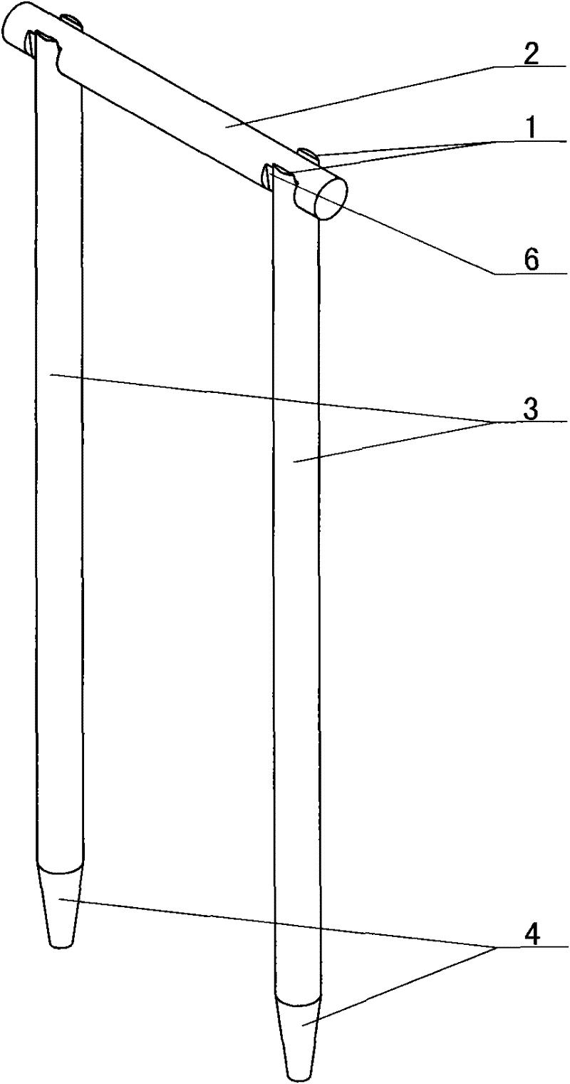
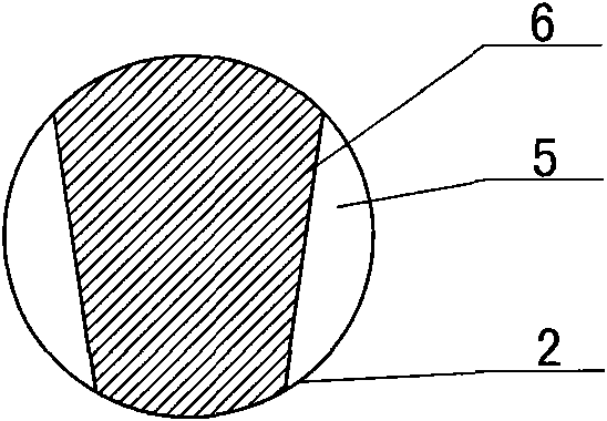
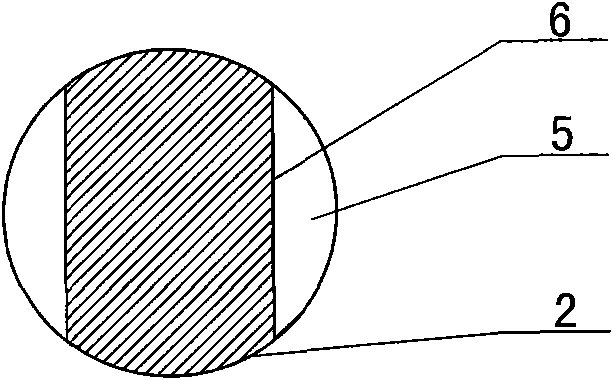
[0041] combined with Figure 1-14The plug-in silicon core overlapping structure that can increase the contact area and reduce resistance includes a horizontal silicon core 2 and two vertical silicon cores 3, and double-sided slots are respectively arranged on both sides of the horizontal silicon core 2 The overlapping surface 6 formed by 5 or set as the end "U" bayonet 7; the upper ends of the two vertical silicon cores 3 are respectively provided with the overlapping surface 6 formed by the double-sided groove 5 or set as the end "U" card mouth 7; when both sides of the horizontal silicon core 2 are set as overlapping surfaces 6 of double-sided grooves 5, the upper ends of the two vertical silicon cores 3 are respectively set as end "U" bayonets 7 or the When the two ends of the horizontal silicon core 2 are set ...


PUM


Abstract

The invention belongs to a silicon core lapping method in a polysilicon production process by a Siemens method, and particularly relates to a socket joint type silicon core lapping structure and method capable of increasing contact area and reducing electric resistance. Both sides of a horizontal silicon core (2) are respectively provided with a lapping surface (6) formed by a bifacial trough (5), or provided with an end U bayonet (7); and the upper ends of two vertical silicon cores (3) are respectively provided with a lapping surface (6) formed by a bifacial trough (5), or provided with an end U bayonet (7). The lapping method comprises the following steps: preprocessing the horizontal silicon core and vertical silicon cores; and after lapping the silicon cores, putting the silicon cores in a reducing furnace, and introducing hydrogen and trichlorosilane to carry out reducing reaction, so that required polysilicon forms the silicon core on the silicon core surface, thereby implementing multiple reduction processes of polysilicon. By using the invention, the lap joint of the silicon cores has large contact surface, and the step of drawing silicon core spherosome in all existing techniques is not needed, thereby ensuring the increase of yield.

Description

【Technical field】 [0001] The invention belongs to a silicon core overlapping method in the process of producing polysilicon by the Siemens method, in particular to a plug-in silicon core overlapping structure and method which can increase the contact area and reduce resistance. 【Background technique】 [0002] At present, silicon core bonding technology is a very important technology in the process of polysilicon production by Siemens method. It is mainly used in a link of polysilicon production, that is, the reduction reaction process. The principle of the reduction reaction process is: the reduction reaction is carried out in a closed reduction furnace, and several closed loops are formed by lapping silicon cores in the reduction furnace before loading the furnace, which is the "bridge" in the jargon. "; each closed circuit is composed of two vertical silicon cores and one horizontal silicon core; the two vertical silicon cores of each closed circuit are respectively connec...

Claims


Application Information

Patent Timeline
Patent Type & Authority Applications(China)
IPC IPC(8): C01B33/035
Inventor 刘朝轩王晨光
Owner LUOYANG JINNUO MECHANICAL ENG
Why Eureka
Try Eureka