Method for calibrating phase of DQS (bidirectional data strobe) delay for DDR (double data rate) controller and apparatus thereof

A phase calibration and controller technology, applied in the phase calibration field of DQS delay, can solve the problems of accuracy dependence, insufficient stability and accuracy, affecting DDR data reading, etc., and achieve high delay accuracy, enhanced stability and anti-interference. Effect

Active Publication Date: 2012-02-08
LEADCORE TECH
View PDF4 Cites 40 Cited by
  • Summary
  • Abstract
  • Description
  • Claims
  • Application Information

AI Technical Summary

Problems solved by technology

This method has at least the following disadvantages: the phase detector 101 has a fixed delay of 1 / 4SDCLK ​​cycle, ignoring the reason of PCB layout and wiring, and the reason of MEMORY (storage) chip timing drift, the position of the DQ effective data sampling window caused may not necessarily fall on the 1 / 4SDCLK ​​cycle delay of DQS at
[0006] In addition, when the phase difference exceeds the preset range of the software, the hardware will automatically update the phase difference, but since the working clock of the phase detector 101 is the interface clock SDCLK, the accuracy of the output result of the phase detector 101 depends on the frequency of SDCLK
Generally, when the frequency of the interface clock SDCLK ​​is greater than 100 MHz, the DQS delayed according to the output result of the phase detector 101 can achieve a relatively accurate 1 / 4 phase delay, but when the frequency of the interface clock SDCLK ​​is lower than 100 MHz, the DQS based on the phase detection The delayed DQS of the output result of the device 101 is generally on the left side of the 1 / 4 SDCLK ​​cycle delay, and the lower the frequency of the interface clock SDCLK, the greater the error of the 1 / 4 cycle delay of DQS
[0007] Therefore, using the DDL delay technology in the prior art and the phase detection technology combined with software and hardware, it is easy to make the phase delay of DQS unstable and generate large errors, which will affect the reading of DDR data and make it not stable and accurate enough.

Method used


Image

  • Method for calibrating phase of DQS (bidirectional data strobe) delay for DDR (double data rate) controller and apparatus thereof
  • Method for calibrating phase of DQS (bidirectional data strobe) delay for DDR (double data rate) controller and apparatus thereof
  • Method for calibrating phase of DQS (bidirectional data strobe) delay for DDR (double data rate) controller and apparatus thereof

Examples


Embodiment Construction

[0047] For reference and clarity, descriptions, abbreviations or abbreviations of technical terms used in the following text are summarized as follows:

[0048] DDR: Double Data Rate, double rate synchronous dynamic random access memory;

[0049] DQS: Bidirectional data strobe, bidirectional data filtering signal;

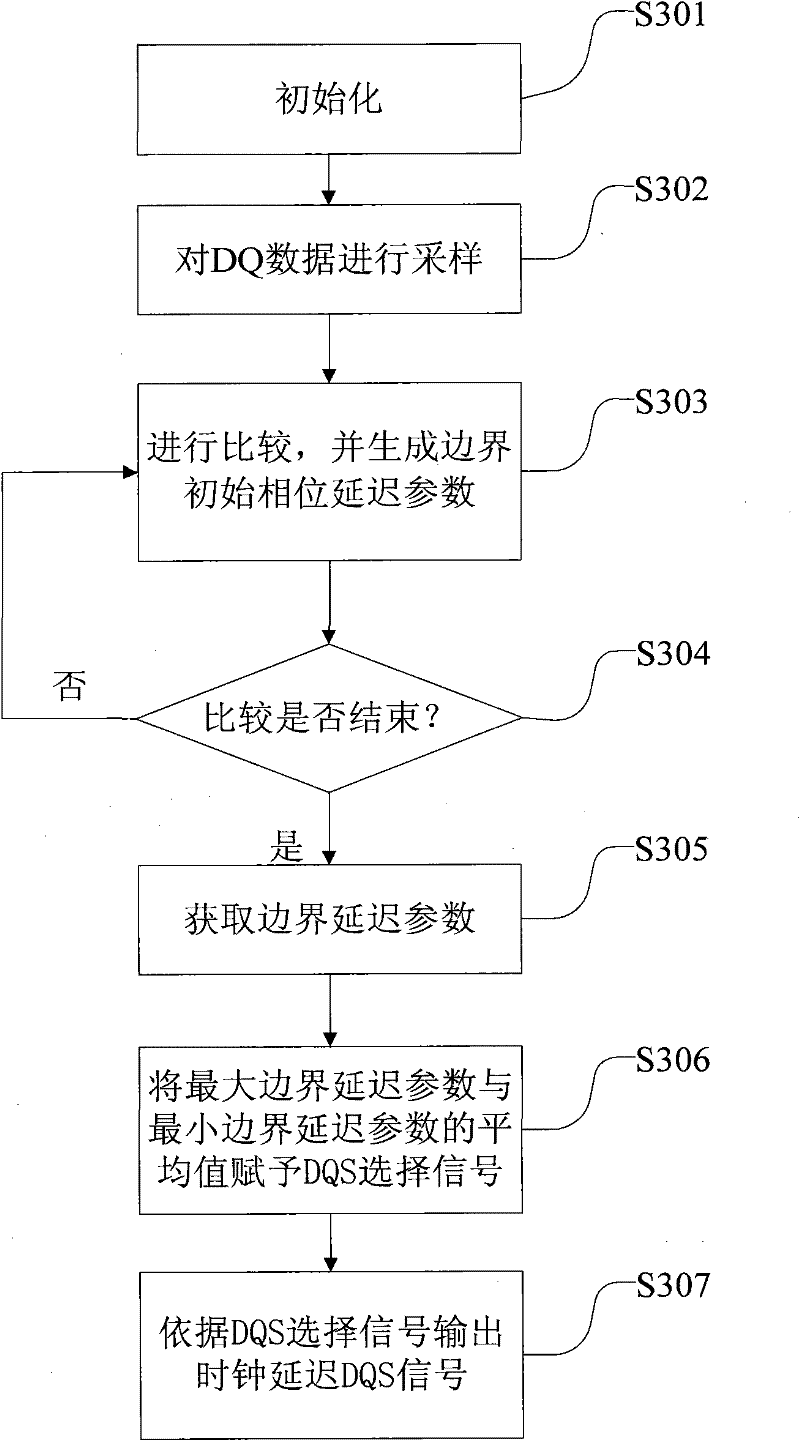
[0050] DLY_Before: the minimum boundary delay parameter;

[0051] DLY_Last: the maximum boundary delay parameter;

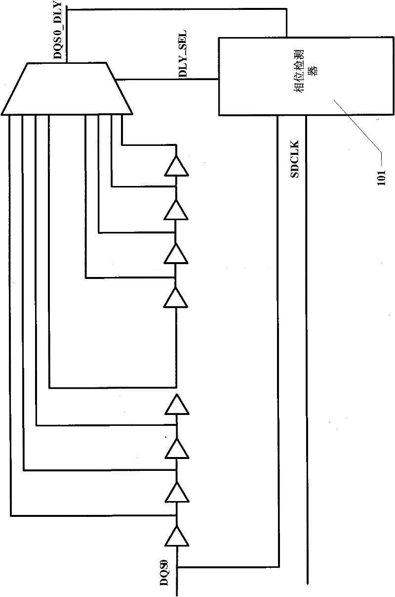
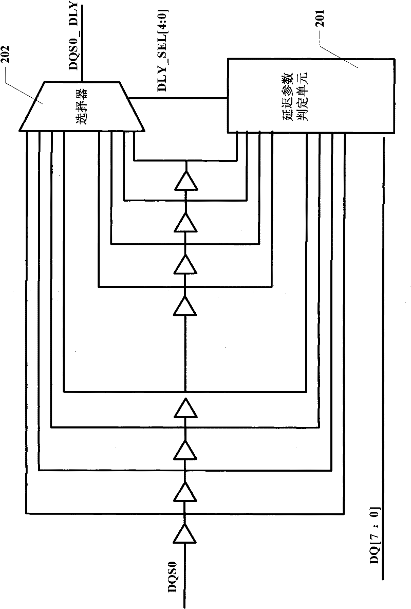
[0052] DQS_DLY: delay the DQS signal for the clock;

[0053] DQS_SEL: select signal for DQS;

[0054] MEMORY chip: memory storage chip;

[0055] In the text, the symbol ">>" means to move one bit to the right.

[0056] The following will clearly and completely describe the technical solutions in the embodiments of the present invention with reference to the accompanying drawings in the embodiments of the present invention. Obviously, the described embodiments are only some, not all, embodiments of the present invention. Based on the embodiments ...


PUM


Abstract

The invention discloses a phase calibration method of the DQS delay for a DDR controller and an apparatus thereof. The method comprises the following steps: 1, sampling DDR data DQ according to trigger signals after different grade delays of a DQS signal; 2, comparing the data DQ acquired by sampling with a preset self-check datum in byte, and acquiring a minimum boundary delay parameter and a maximum boundary delay parameter through delaying for two beats; 3, endowing a mean value of the minimum boundary delay parameter and the maximum boundary delay parameter to a DQS selection signal; and 4, delaying the DQS signal according to the output clock of the DQS selection signal to obtain a DQS signal at the center of an effective datum window. According to the invention, the phase calibration of the DQS delay is realized through adopting a delay parameter determination unit and hardware in a delay parameter output circuit, and the delayed DQS can accurately fall on the center of the effective datum window through a datum screening method with the delay parameter determination unit, thereby the stability, the accuracy and the interference immunity of datum sampling are enhanced.

Description

technical field [0001] The present invention relates to the technical field of communication, and more specifically relates to a DQS delay phase calibration method and device applied in a DDR controller. Background technique [0002] With the rapid development of portable devices and mobile terminal products, various applications previously applied to PCs (Personal Computers, personal computers) are also applied to handheld terminals, and more and more such applications are becoming more and more popular. It is becoming more and more complex, and the complexity of the application will inevitably require that the memory access bandwidth of the baseband processor and application processor applied to the handheld terminal is large enough, so that DDR (Double Data Rate, double-rate synchronous dynamic random access memory) More and more applications of the controller are used on the baseband chip, application processor chip or SOC chip of the handheld terminal. [0003] DQS (Bi...

Claims


Application Information

Patent Timeline
Patent Type & Authority Applications(China)
IPC IPC(8): G11C29/02
Inventor 史公正
Owner LEADCORE TECH
Why Eureka
Try Eureka