Supercharger applicable to steel pipe water-pressure test system

A hydraulic test and supercharger technology, applied in fluid pressure converters, by detecting the appearance of fluid at the leak point, using liquid/vacuum degree for liquid tightness measurement, etc., can solve the problem of seal wear, damage, pollution Water system and other problems, to achieve the effect of simple structure and convenient maintenance

Active Publication Date: 2012-02-15
CHINA NAT HEAVY MACHINERY RES INSTCO
View PDF5 Cites 7 Cited by
  • Summary
  • Abstract
  • Description
  • Claims
  • Application Information

AI Technical Summary

Problems solved by technology

The structure of the existing supercharger, such as figure 1 As shown, it is mainly composed of hydraulic cylinder 1, hydraulic piston 2, hydraulic seal 3, pressure ring 4, hydraulic seal 5, connector 6 and hydraulic cylinder 7, etc. This structure has certain disadvantages: Both the oil pressure seal 3 and the water pressure seal 5 are designed inside the supercharger, and the seals will definitely be worn and damaged during long-term work, and even cause the hydraulic oil and pressure test water to pass through the cavity, so It has caused great difficulty in the maintenance and maintenance of the supercharger
[0003] The usual solution to the wear and damage of the seals is to replace the seals regularly, but the damage of the seals is accidental. After the damage occurs, it is difficult for the maintenance personnel to judge whether the damage is an oil pressure seal or a water pressure seal, and oil-water mixing is prone to occur
If water enters the hydraulic system, the hydraulic oil will deteriorate and emulsify, which will affect the normal operation of the hydraulic system; otherwise, the hydraulic oil will pollute the water system and the hydraulic test cannot be carried out as required.
[0004] Therefore, the supercharger of the existing structure is not only difficult to maintain, but also causes great economic losses

Method used


Image

  • Supercharger applicable to steel pipe water-pressure test system
  • Supercharger applicable to steel pipe water-pressure test system
  • Supercharger applicable to steel pipe water-pressure test system

Examples


Embodiment Construction

[0019] The invention relates to a supercharging device, in particular to a device for testing the pressure resistance of a steel pipe body, which is suitable for a steel pipe hydraulic test system.

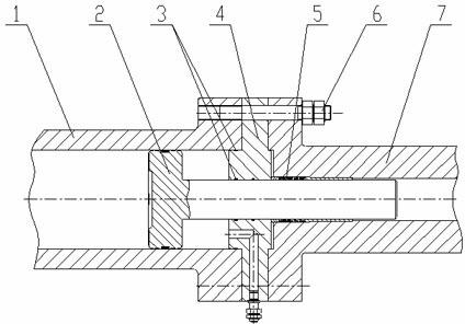
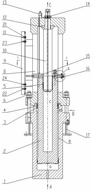
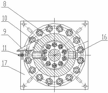
[0020] see Figure 2 to Figure 4 , the structure of the present invention is as follows:

[0021] A supercharger suitable for a steel pipe hydrostatic test system, including an oil pressure part, a water pressure part, a detection part and a fixing bracket 17;

[0022] The hydraulic part is composed of hydraulic cylinder 1, hydraulic piston 2, hydraulic seal 3 and pressure ring 4, which are assembled into a piston cylinder; wherein, hydraulic cylinder 1 and fixed bracket 17 are connected through connecting pieces; The oil pressure piston 2 is installed inside the oil pressure cylinder 1; the pressure ring 4 is installed between the oil pressure cylinder 1 and the oil pressure piston 2, and the oil pressure seal 3 is installed on the pressure ring 4; the oil pressure cylinder 1 i...


PUM


Abstract

The invention relates to metallurgical equipment, in particular to a supercharger in a steel pipe water-pressure test system. The supercharger is characterized by comprising an oil pressure part, a water pressure part, a detecting part and a fixed bracket, wherein the oil pressure part comprises an oil pressure cylinder body, an oil pressure piston, an oil pressure seal and a pressing ring which are assembled into a piston cylinder; the oil pressure cylinder body is connected with the fixed bracket by a connecting piece; the oil pressure piston is arranged in the oil pressure cylinder body in a matching manner; the pressing ring is arranged between the oil pressure cylinder body and the oil pressure piston in a matching manner; the oil pressure seal is arranged on the pressing ring; the oil pressure cylinder body is provided with a hydraulic oil opening A on the bottom part of the oil pressure cylinder body and a hydraulic oil opening B on the side wall of the oil pressure cylinder body; and the water pressure part consists of an oil pressure piston, a water pressure seal, a water pressure supporting barrel, a water pressure cylinder plunger, a cushion plate, a nut and a pressing plate which are assembled into a plunger cylinder. In the supercharger applicable to the steel pipe water-pressure test system provided by the invention, the structure is simple, the maintenance is convenient, the damage of a sealing piece can be found in time, and whether the oil pressure seal or the water pressure seal is damaged can be accurately judged.

Description

technical field [0001] The invention relates to metallurgical equipment, in particular to a supercharger in a steel pipe hydraulic test system. Background technique [0002] The supercharger is the key device in the steel pipe hydrostatic test system. The supercharger used in the hydrostatic testing machine uses the oil pressure to pass the area ratio between the pistons to realize the pressurization of the hydraulic system. Both are composed of oil pressure and water pressure. Composed of two parts. The structure of the existing supercharger, such as figure 1 As shown, it is mainly composed of hydraulic cylinder 1, hydraulic piston 2, hydraulic seal 3, pressure ring 4, hydraulic seal 5, connector 6 and hydraulic cylinder 7, etc. This structure has certain disadvantages: Both the oil pressure seal 3 and the water pressure seal 5 are designed inside the supercharger, and the seals will definitely be worn and damaged during long-term work, and even cause the hydraulic oil an...

Claims


Application Information

Patent Timeline
Patent Type & Authority Applications(China)
IPC IPC(8): F15B3/00G01M3/04
Inventor 杜学斌刘继高权晓惠卫凌云
Owner CHINA NAT HEAVY MACHINERY RES INSTCO
Why Eureka
Try Eureka