Household floor gas furnace

A floor-to-ceiling furnace and gas technology, applied in household heating, household heating, household appliances, etc., can solve the problems of small heating area, poor safety, low thermal efficiency, etc.

Inactive Publication Date: 2012-02-15
王文茂
View PDF5 Cites 5 Cited by
  • Summary
  • Abstract
  • Description
  • Claims
  • Application Information

AI Technical Summary

Problems solved by technology

[0003] In order to solve the problems of small heating area, uneven heating, low thermal efficiency, high cost and poor safety of existing gas-fired heating equipment, the present invention provides a household gas-fired floor-standing furnace

Method used


Image

  • Household floor gas furnace
  • Household floor gas furnace
  • Household floor gas furnace

Examples


Embodiment Construction

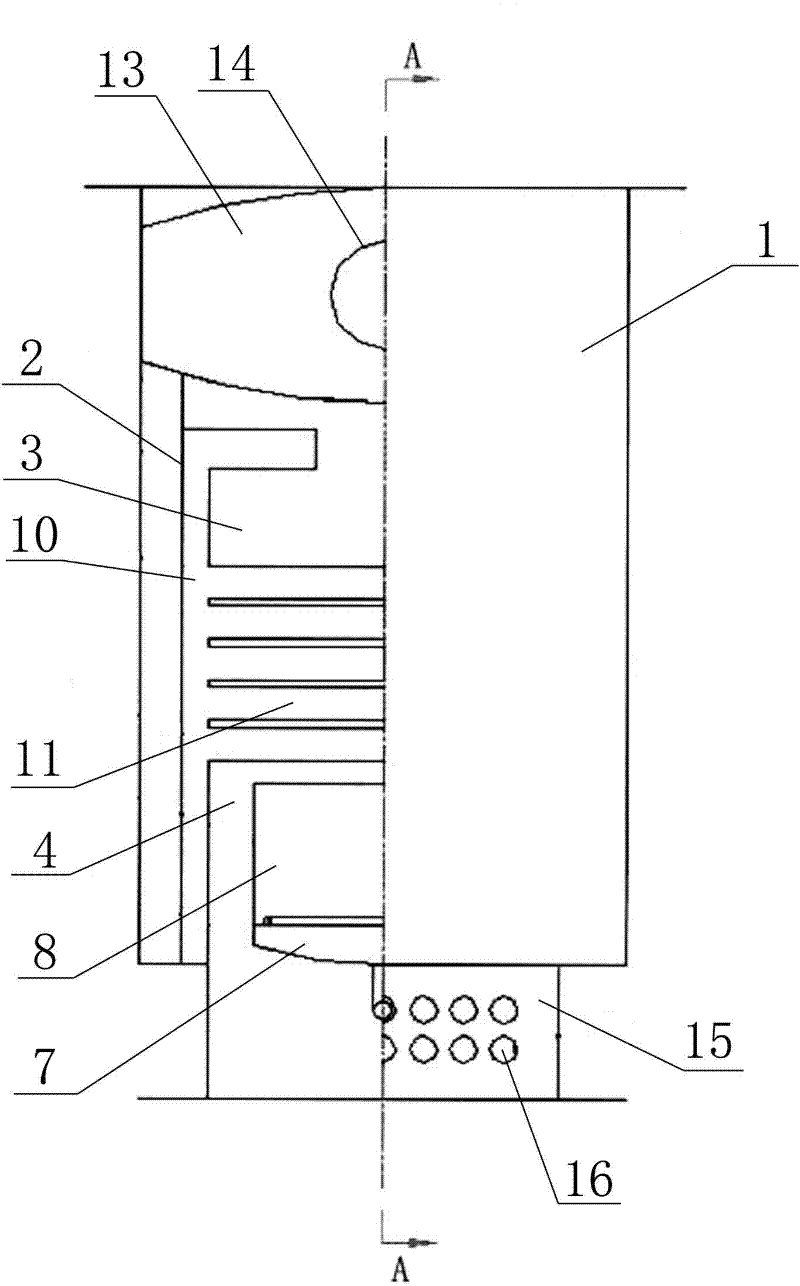
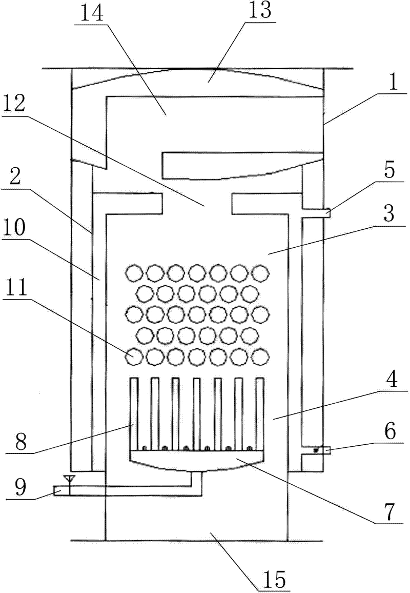
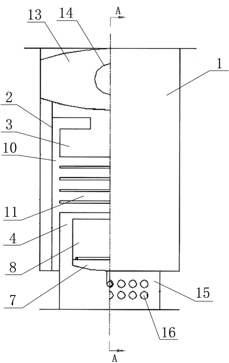
[0011] A household gas-fired floor-standing furnace includes a furnace shell 1, a furnace body 2 disposed in the furnace shell 1, a furnace 3 disposed in the furnace body 2, and a combustion chamber 4 disposed below the furnace 3; A water outlet 5 and a water return port 6; a burner 7 is installed in the combustion chamber 4; a combustion grate 8 is installed on the top of the burner 7, and a gas inlet 9 is provided at the bottom of the burner 7; There is a water jacket 10; a layered tube heat exchanger composed of a heat exchange tube array is installed in the furnace 3, and the heat exchange tube array includes several heat exchange tubes 11 arranged horizontally and fixed in the furnace 3 and parallel to each other; The pipes 11 are all in communication with the water jacket 10; the top of the furnace 3 has an exhaust port 12; the upper end of the furnace body 2 is fixed with a waste heat absorption water tank 13, and a waste heat recovery pipe 14 is installed in the waste h...


PUM


Abstract

The invention relates to gas heating equipment, in particular to a household floor gas furnace. The invention solves the problems of small heating area, nonuniform heating, low thermal efficiency, high cost and low safety of the conventional gas heating equipment. The household floor gas furnace comprises a furnace shell, a furnace body arranged in the furnace shell, a furnace cavity arranged in the furnace body, and a combustion chamber arranged below the furnace cavity, wherein a water jacket is arranged between the outer wall of the furnace body and the inner wall of the furnace body; a layered pipe heat exchanger consisting of a heat exchange pipe array is arranged in the furnace cavity; the heat exchange pipe array comprises a plurality of heat exchange pipes which are horizontally and fixedly arranged in the furnace cavity; an excess heat absorption water tank is fixed at the upper end of the furnace body; and an excess heat recovery pipe is arranged in the excess heat absorption water tank. The household floor gas furnace adopts a new heat exchange structure, effectively solves the problems of small heating area, nonuniform heating, low thermal efficiency, high cost and low safety of the conventional gas heating equipment, and is suitable for household gas heating.

Description

technical field [0001] The invention relates to gas-fired heating equipment, in particular to a household gas floor-standing furnace. Background technique [0002] With the popularization of natural gas and coalbed methane, gas-fired heating equipment has been more and more widely used due to its advantages of low emission and convenient use. Existing gas-fired heating equipment is mainly divided into wall-hung boilers and gas-fired hot water heating boilers. Among them, the wall-hung boiler must be powered on when it is used, which leads to high cost and is not conducive to popularization and promotion. Due to the limitation of its own structure, the gas-fired hot water heating boiler has the problems of small heating area, uneven heating, and low thermal efficiency, which is easy to cause energy waste. , Moreover, during the use of the gas-fired hot water heating boiler, unburned gas is likely to remain in the furnace body, which is likely to cause safety hazards. Based ...

Claims


Application Information

Patent Timeline
Patent Type & Authority Applications(China)
IPC IPC(8): F24D15/00F24D19/00
Inventor 王文茂
Owner 王文茂
Why Eureka
Try Eureka