Cylindrical-cavity type solar heat absorber with internally-convex bottom surface

A solar heat absorber and heat absorber technology, which is applied to solar heat collectors, solar heat collectors using working fluids, solar heat energy, etc., can solve the problem that metal tubes are difficult to cover the entire bottom surface.

Active Publication Date: 2012-02-15
HARBIN INST OF TECH
View PDF7 Cites 23 Cited by
  • Summary
  • Abstract
  • Description
  • Claims
  • Application Information

AI Technical Summary

Problems solved by technology

[0005] The purpose of the present invention is to solve the problem that the metal tube at the bottom surface of the existing cylindrical cavity type heat absorber is difficult to cover the entir

Method used


Image

  • Cylindrical-cavity type solar heat absorber with internally-convex bottom surface
  • Cylindrical-cavity type solar heat absorber with internally-convex bottom surface
  • Cylindrical-cavity type solar heat absorber with internally-convex bottom surface

Examples


specific Embodiment approach 1

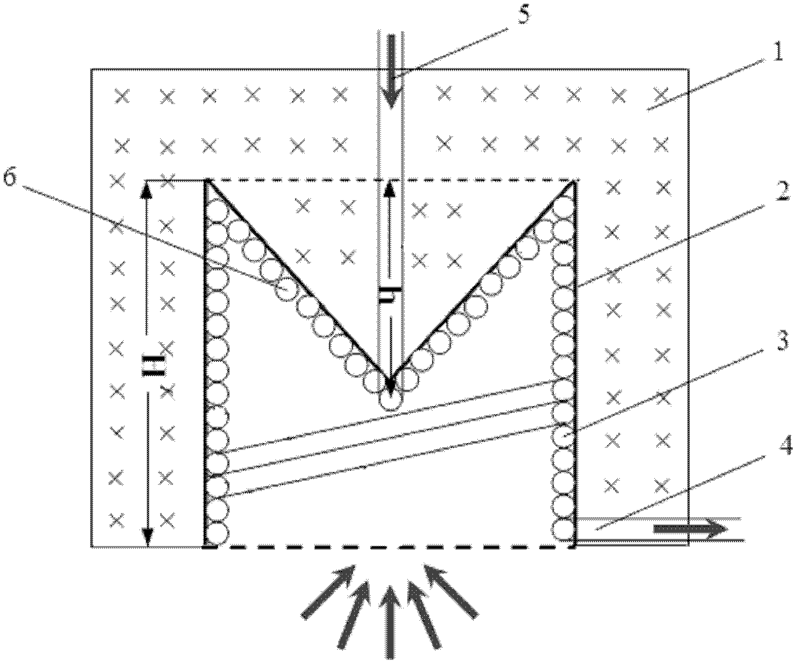
[0009] Specific implementation mode one: combine figure 1 To illustrate this embodiment, a cylindrical cavity-type solar heat absorber with an inner convex bottom surface of this embodiment includes a slag wool insulation layer 1, a heat absorber shell 2, a side coil 3 of the heat absorber, and a working medium outlet pipe 4 , the working medium inlet pipe 5 and the inner convex segment coil 6 on the bottom surface of the heat absorber. The bottom surface of the heat absorber shell 2 has a V-shaped structure, the side coil 3 of the heat absorber is wound on the side inner wall of the heat absorber shell 2, and the coil 6 of the convex section in the bottom surface of the heat absorber is wound on the On the bottom surface of the heat absorber shell 2, the inlet end of the coil pipe 3 on the side of the heat absorber communicates with the outlet end of the raised section coil pipe 6 in the bottom surface of the heat absorber, and on the outer surface of the heat absorber shell ...

specific Embodiment approach 2

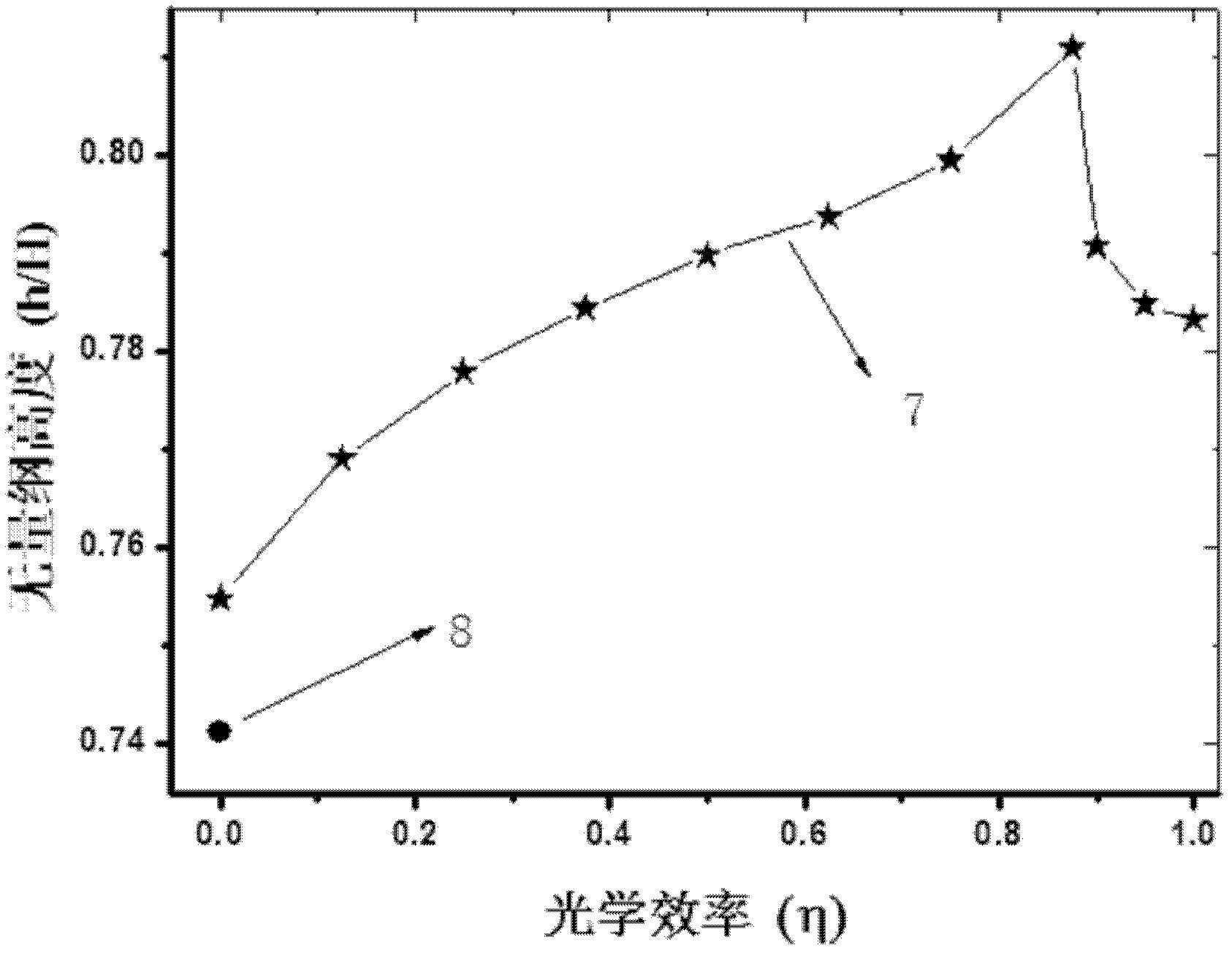
[0010] Specific implementation mode two: combination figure 1 The present embodiment will be described. The ratio of the bottom surface protrusion height h of the heat absorber case 2 to the height H of the heat absorber case 2 of the present embodiment is 0.75 to 1. With such arrangement, the optical efficiency of the solar heat absorber varies with the dimensionless height h / H of the protrusion inside the bottom coil tube. Other compositions and connections are the same as in the first embodiment.

specific Embodiment approach 3

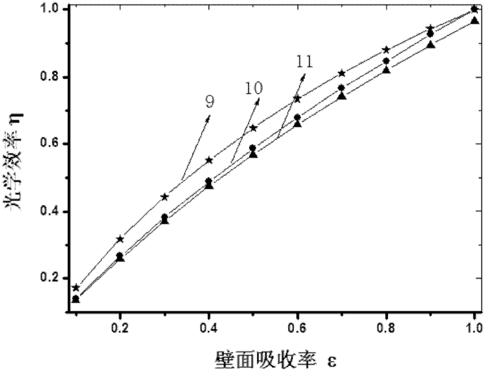
[0011] Specific implementation mode three: combination figure 1 The present embodiment will be described. The ratio of the bottom surface protrusion height h of the heat absorber case 2 to the height H of the heat absorber case 2 of the present embodiment is 1. FIG. In this way, when the wall absorptivity is 0.7 and h / H=1, the optical efficiency of the bottom surface convex cylindrical cavity type solar heat absorber is 78.331%, which is better than the ideal of the metal tube at the bottom surface of the heat absorber coiling the entire bottom surface. In this case, the optical efficiency of the cylindrical cavity absorber is 2.848% higher. Other compositions and connections are the same as those in the second embodiment.


PUM


Abstract

The invention discloses a cylindrical-cavity type solar heat absorber with an internally-convex bottom surface, relating to a solar heat absorber and aiming at solving the problem that metal pipes at the bottom surface of the cylindrical-cavity type heat absorber are difficult to be full of the bottom surface, and a dead zone of absorption of solar radiant heat flux, of the solar absorber exists.The bottom surface of a heat absorber shell is an internally-convex structure, the bottom surface of the heat absorber shell is in a V-shaped structure, coil pipes on the lateral surface part of the heat absorber are wound on the inner wall of the lateral surface of the heat absorber shell, coiling pipes on the internally-convex section of the bottom surface of the heat absorber are wounded on the bottom surface of the heat absorber shell, and the inlet end of the coil pipes on the lateral surface part of the heat absorber is communicated with the outlet end of the coil pipes at the internally-convex section of the bottom surface of the heat absorber; a mineral cotton insulation layer is arranged on the outer surface of the heat absorber shell; a working medium outlet pipe is penetratively arranged in the mineral cotton insulation layer and communicated with the outlet end of the coil pipes on the lateral surface part of the heat absorber; and a working medium inlet pipe is penetratively arranged in the mineral cotton insulation layer and communicated with the inlet end of the coil pipes at the internally-convex section of the bottom surface of the heat absorber. The invention is used for absorbing solar energy.

Description

technical field [0001] The invention relates to a solar heat absorber, in particular to a cylindrical cavity type solar heat absorber with an inner convex bottom surface, which belongs to the technical field of solar heat utilization. Background technique [0002] Solar thermal utilization is one of the effective ways to develop renewable energy. At present, there are three main forms of solar thermal power concentrating technology in the world: trough type, tower type and dish type. The trough solar thermal power generation technology is already a mature commercial technology, while the tower and dish solar thermal power generation technologies are still in the test and demonstration stage. [0003] The concentrator in the solar thermal power generation system utilizes its own geometrical optical characteristics to gather the sunlight with low radiant heat flux density to form a high radiant heat flux density. The cavity heat absorber placed at the focal point of the conc...

Claims


Application Information

Patent Timeline
IPC IPC(8): F24J2/24F24J2/46F24S10/70
CPCY02E10/44
Inventor 王富强帅永袁远刘彬谈和平
Owner HARBIN INST OF TECH
Why Eureka
Try Eureka