Delay amount measuring method applied for fiber delay line measuring system and realization apparatus thereof

A technology of optical fiber delay line and measurement method, which is applied in the direction of testing optical performance, etc., can solve the problems of large delay measurement error and low precision of optical fiber delay line, and achieve high precision, fast high-precision measurement, and easy high-precision measurement Effect

Inactive Publication Date: 2012-02-15
BEIHANG UNIV
View PDF5 Cites 8 Cited by
  • Summary
  • Abstract
  • Description
  • Claims
  • Application Information

AI Technical Summary

Problems solved by technology

[0004] In order to solve the problems of large measurement errors and low precision of the delay of optical fiber delay lines in the prior art, the present invention proposes a delay measurement method applicable to an optical fiber delay line measurement system and its implementation device. The measurement method can be As a benchmark for fiber optic delay line measurement systems

Method used


Image

  • Delay amount measuring method applied for fiber delay line measuring system and realization apparatus thereof
  • Delay amount measuring method applied for fiber delay line measuring system and realization apparatus thereof
  • Delay amount measuring method applied for fiber delay line measuring system and realization apparatus thereof

Examples


Embodiment Construction

[0023] The measuring method and its implementation device provided by the present invention will be described in detail below in conjunction with the accompanying drawings and embodiments.

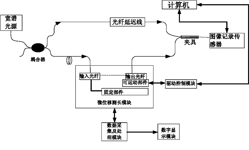
[0024] The present invention firstly provides a delay measurement method for an optical fiber delay line measurement system, and the measurement method is specifically implemented through the following steps:

[0025] In the first step, the light emitted by the wide-spectrum light source is divided into two paths by the 3dB coupler. The first path is used as the measurement arm to enter the fiber delay line of predetermined length, and the second path is connected to the input optical fiber of the micro-displacement length measurement module. After the output optical fiber of the micro-displacement length measurement module and the predetermined length optical fiber delay line are fixed by the clamp, they are connected to the image recording sensor, and the image recording sensor adopts a s...


PUM


Abstract

The invention, which belongs to the fiber measurement technology field, disclose a delay amount measuring method applied for a fiber delay line measuring system and a realization apparatus thereof. The measuring method comprises the following steps that: a light that is emitted by a broadband light source passes through a 3dB coupler and is divided into two paths of lights, wherein a first path of the light passes through a fiber and a second path of the light passes through a micro displacement measurement length module; and a delay amount of a to-be-detected fiber is obtained according to two interference conditions of the two paths of the light. According to the realization apparatus, an employed image recording sensor is used not only as an image recording sensor but also as an imaging screen, so that a substantial measurement error that is caused by a problem of a recording direction can be avoided; and then the result is sent to a computer to carry out processing. According to the invention, feedback control is employed; and an interference result of an image recording sensor is utilized to control a moving state of a micro displacement measurement length module; moreover, the processing speed is fast and the precision is high; automatic adjustment can be realized and high-precision measurement is easy to realize.

Description

technical field [0001] The invention relates to a measurement method in the technical fields of machinery, sensors and automation, in particular to a reference or high-precision measurement method of an optical fiber delay line applied to an optical fiber delay line measurement system and an implementation device thereof. Background technique [0002] The currently reported measurement methods for the delay of optical fiber delay lines are mainly electronic measurement methods and optical measurement methods. The electronic measurement method is suitable for microwave fiber delay line components with electrical-optical-electrical conversion functions. The measurement results are obtained by a high-speed oscilloscope or a vector network analyzer. Due to the limitation of the accuracy of the instrument, only relatively small Waveforms with a long time delay. For all-optical fiber delay lines, according to whether interference is used in the measurement principle, optical meas...

Claims


Application Information

Patent Timeline
Patent Type & Authority Applications(China)
IPC IPC(8): G01M11/02
Inventor 胡姝玲黄杰刘宏海苑丹丹王鑫龙
Owner BEIHANG UNIV
Why Eureka
Try Eureka