Transient unloading loose simulating system for excavating jointed rock mass

A technology for transient unloading, loosening, and jointed rock mass. It is used in material inspection products, soil material testing and other directions. It can solve the problem of slow unloading rate of unloading experimental system, unsatisfactory engineering unloading conditions, and joint rock model strain rate. lower problem

Active Publication Date: 2012-02-15
WUHAN UNIV
View PDF8 Cites 18 Cited by
  • Summary
  • Abstract
  • Description
  • Claims
  • Application Information

AI Technical Summary

Problems solved by technology

Excavation changes the geometric shape of the original jointed rock mass, which removes all or part of the initial stress on the excavation surface, causing changes in the boundary conditions and load conditions of the jointed rock mass, which may cause serious stability or deformation of the jointed rock mass control puzzle
[0003] However, in the past research methods on the transient unloading and loosening of jointed rock mass excavation, generally through theoretical analysis or numerical simulation, it is impossible to intuitively understand the strain of the jointed rock mass during the transient unloading and loosening process of jointed rock mass excavation , displacement and vibration, and the existing unloading test system has a slow unloading rate, which cannot quickly unload the load on the jointed rock mass model, so the strain rate of the jointed rock mass model is low during unloading , does not conform to the actual unloading situation in the project

Method used


Image

  • Transient unloading loose simulating system for excavating jointed rock mass
  • Transient unloading loose simulating system for excavating jointed rock mass
  • Transient unloading loose simulating system for excavating jointed rock mass

Examples


Embodiment Construction

[0033] The specific implementation of the present invention will be further described below in conjunction with the accompanying drawings.

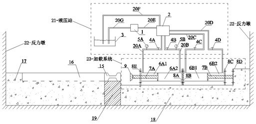
[0034] like figure 1 As shown, the present invention includes: a reaction pier (22), a jointed rock mass model, a test bench (17) provided with displacement scale marks, a transition block pad box (19), a pad box placed on the transition block pad box (19) Transition block (15), hydraulic station (21), loading device (23), loading device support table (18) and monitoring system.

[0035] Both the test platform (17) and the loading device support platform (18) are poured with high-strength concrete, such as Figure 7~8 As shown, the test bench (17) is 1.2m long, 0.5m wide, and 0.4m high, and a groove with a length of 1.0m, a width of 0.1m, and a height of 0.1m is arranged in the middle of the broad side of the upper surface of the test bench (17), for The jointed rock mass model is placed, and the width and height of the jointed rock mas...


PUM


Abstract

The invention discloses a transient unloading loose simulating system for excavating a jointed rock mass. The transient unloading loose simulating system for excavating the jointed rock mass comprises counterforce piers, a jointed rock mass model, an experimental table provided with displacement scale marks, a transitional block cushioning box, a transitional block arranged on the transitional block cushioning box, a hydraulic station, a loading device, a loading device supporting table and a monitoring system, wherein the counterforce piers are fixed on the outer sides of the loading device supporting table and the experimental table; the transitional block cushioning box is arranged on the other side of the experimental table; a slot for accommodating the jointed rock mass model is formed on the upper surface of the experimental table; the transitional block (15) is a square column with a variable cross section, and the section areas of the two ends of the transitional block are larger than the section area of the middle section; the width and height of the jointed rock mass model are matched with those of the transitional block (15); the loading device is horizontally arranged on the loading device supporting table; and the monitoring system is used for monitoring the simulating process. By the system, the load on the jointed rock mass model is quickly unloaded, and the actual unloading condition in an engineering is met well.

Description

technical field [0001] The invention belongs to the field of geotechnical engineering model experiment devices, in particular to a simulation system for transient unloading and loosening of jointed rock mass excavation. Background technique [0002] Rocks in nature are often cut by joints after long-term tectonic movement and human disturbance, that is, jointed rock mass. However, under the condition of high ground stress, excavation disturbance will lead to strong unloading and stress redistribution of rock mass, especially when excavating jointed rock mass, it often shows the loosening effect of jointed rock mass. Excavation changes the geometric shape of the original jointed rock mass, which removes all or part of the initial stress on the excavation surface, causing changes in the boundary conditions and load conditions of the jointed rock mass, which may cause serious stability or deformation of the jointed rock mass Control puzzles. [0003] However, in the past rese...

Claims


Application Information

Patent Timeline
Patent Type & Authority Applications(China)
IPC IPC(8): G01N33/24
Inventor 卢文波罗忆陈明严鹏周创兵李典庆陈益峰
Owner WUHAN UNIV
Why Eureka
Try Eureka