Fault distance measuring method for combined travelling wave of power transmission line

A technology of transmission lines and ranging methods, applied in radio wave measurement systems, fault locations, measuring devices, etc., can solve the reliability and accuracy of given line length errors, influences, and unreliable ranging results of the double-ended principle, etc. problems, to achieve the effect of improving reliability and accuracy, broad application prospects, and improving power supply reliability

Inactive Publication Date: 2012-02-15
SHANDONG UNIV OF TECH
View PDF4 Cites 43 Cited by
  • Summary
  • Abstract
  • Description
  • Claims
  • Application Information

AI Technical Summary

Problems solved by technology

However, theoretical analysis and practical application show that although the double-ended traveling wave principle can automatically give fault location results online, the reliability and accuracy are affected by

Method used


Image

  • Fault distance measuring method for combined travelling wave of power transmission line
  • Fault distance measuring method for combined travelling wave of power transmission line
  • Fault distance measuring method for combined travelling wave of power transmission line

Examples


Embodiment 1

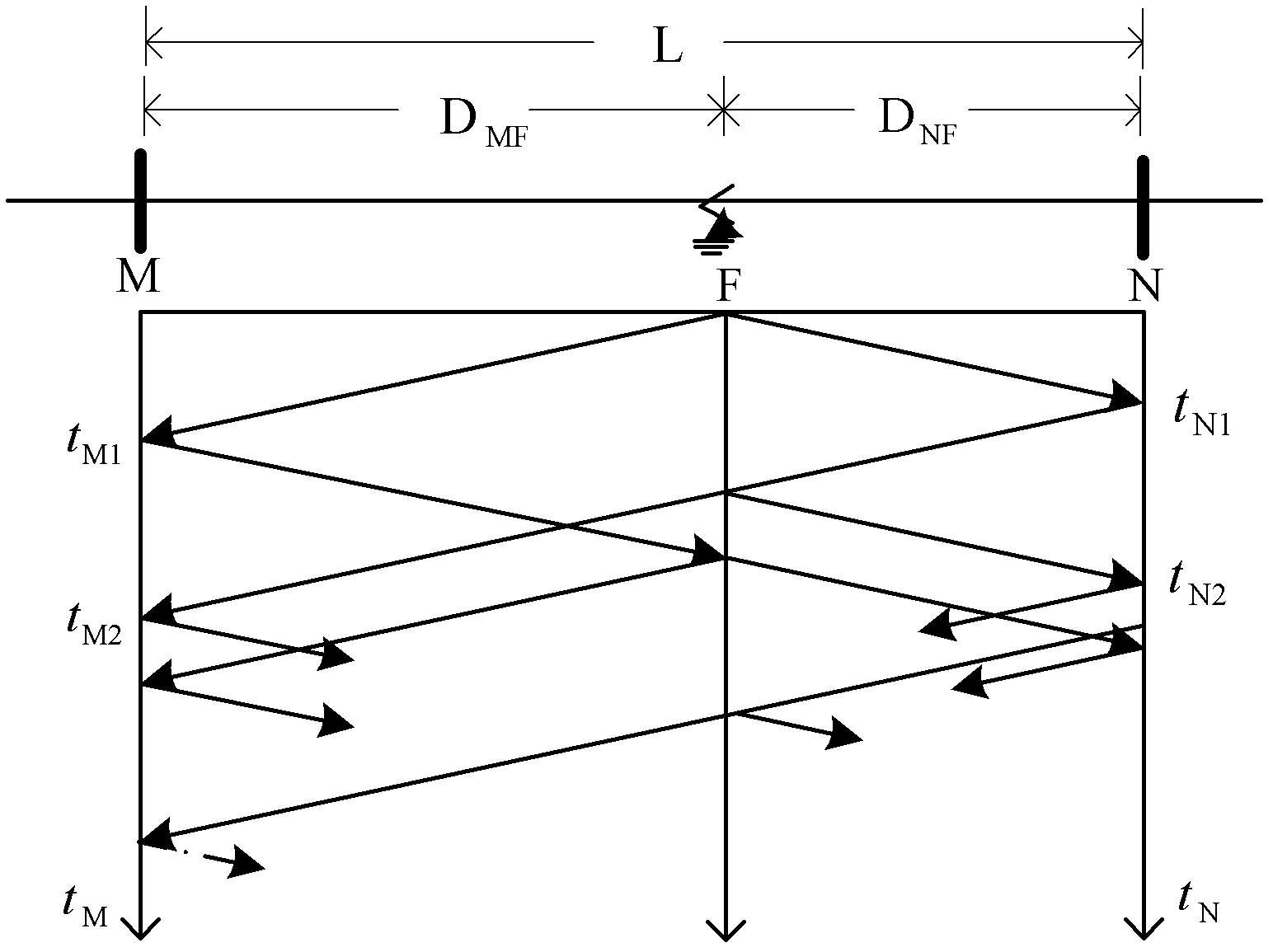
[0015] Embodiment 1: The voltage level is 220kV, M and N are the busbars at both ends of the transmission line, and the length of the transmission line is L=100km, t M1 , t M2 is the time when the fault traveling wave arrives at the M-terminal bus for the first time and the second time after the line fault, t N1 , t N2 is the time when the fault traveling wave arrives at the N-terminal bus for the first time and the second time. The fault point F is 25km away from the M-side busbar, and the wave velocity of the traveling wave in the transmission line is v=295.0813km / ms. A fault occurs at time t=0.

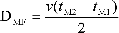
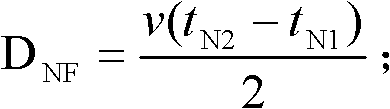
[0016] Step 1. Preliminary test: after the line fault, measure the time t when the fault traveling wave arrives at the M-terminal bus for the first time and the second time M1 = 86μs, t M2 =256μs, the time t for the first and second arrival at the N-terminal bus N1 = 256μs, t N2 = 425 μs. Using the single-ended traveling wave principle to calculate the distance between two ...

Embodiment 2

[0023] Embodiment 2: the voltage level is 220kV, M and N are the busbars at both ends of the transmission line, and the length of the transmission line is L=100km, t M1 , t M2 is the time when the fault traveling wave arrives at the M-terminal bus for the first time and the second time after the line fault, t N1 , t N2 is the time when the fault traveling wave arrives at the N-terminal bus for the first time and the second time. The fault point F is 35km away from the N-terminal bus, and the wave speed of the traveling wave in the transmission line is v=295.0813km / ms. A fault occurs at time t=0.

[0024] Step 1. Preliminary test: after the line fault, measure the time t when the fault traveling wave arrives at the M-terminal bus for the first time and the second time M1 = 222μs, t M2 =458μs, the time t for the first and second arrival at the N-terminal bus N1 = 120μs, t N2 = 357 μs. Using the single-ended traveling wave principle to calculate the distance between two p...


PUM


Abstract

The invention provides a fault distance measuring method for a combined travelling wave of a power transmission line. The method comprises the following steps of: firstly, performing primary fault distance measurement with the single-end principle to obtain two possible fault positions; and then, comparing the time difference of the fault initial travelling wave arriving at the two sides of the line with the time difference of the fault travelling wave arriving at the two ends of the line after the possible fault points fail, so as to obtain the real fault point determined by the single-end travelling wave principle. The method has the advantages that: as the obtained distance measurement result is obtained by the single-end principle, the influence of the mixed line length error caused by the distance measurement adopting the double-end principle and the accurate time synchronization problem between the two sides of the line on the distance measurement accuracy is eliminated, thus the accuracy and reliability of the distance measurement are improved. Through the method, the fault distance measurement for the travelling wave of the power line is realized, and the reliability and accuracy of the travelling wave distance measurement are improved; and after the line fails, the fault point can be found without taking much time, the power supply reliability is improved, and the method has wide application prospects.

Description

technical field [0001] The invention belongs to the technical field of electric power system protection, and in particular relates to a distance measurement method for combined traveling wave faults of transmission lines. Background technique [0002] Quickly and accurately determining the location of the fault point of the power line can speed up the repair of permanent faults, eliminate hidden dangers in time to avoid the recurrence of a large number of transient faults, and is of great significance to ensure the safety, stability and economic operation of the power system. [0003] At present, many methods have been proposed at home and abroad for the fault location of transmission lines, which are mainly divided into two categories: impedance method and traveling wave method according to their principles. The impedance method is affected by factors such as line structure asymmetry, transition resistance, uneven distribution of line parameters along the corridor, and tran...

Claims


Application Information

Patent Timeline
IPC IPC(8): G01R31/08G01S5/00
CPCY04S10/52
Inventor 陈平王奎鑫
Owner SHANDONG UNIV OF TECH
Why Eureka
Try Eureka