Light path collimation integrated device and method for high-power laser device

A technology of optical path collimation and laser device, which is applied in the direction of optics, optical components, instruments, etc., can solve the problems of difficult sampling accuracy, large space occupation, and high cost, so as to save occupied space and required costs, and improve near-field Effect of resolution and far-field angular resolution

Inactive Publication Date: 2012-02-15
上海激光等离子体研究所
View PDF4 Cites 39 Cited by
  • Summary
  • Abstract
  • Description
  • Claims
  • Application Information

AI Technical Summary

Problems solved by technology

This method is costly and takes up a huge amount of space, especially for collimated sampling of large-aperture (above 100 mm) beams. Not only is the implementation cost and technical difficulty unacceptable, but the sampling accuracy is also difficult to guarantee.

Method used


Image

  • Light path collimation integrated device and method for high-power laser device
  • Light path collimation integrated device and method for high-power laser device
  • Light path collimation integrated device and method for high-power laser device

Examples


Embodiment Construction

[0033] The present invention will be further described below in conjunction with example and accompanying drawing, but should not limit protection scope of the present invention with this.

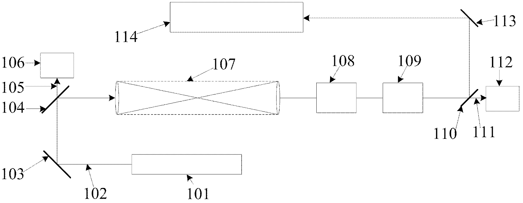
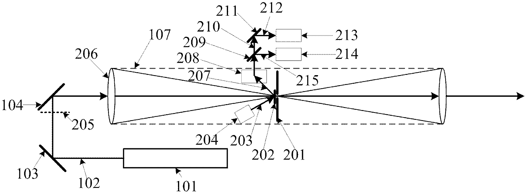
[0034] see first figure 2 and Figure 5 , figure 2 It is a schematic diagram of the optical path of the optical path collimation integrated device used in the high-power laser device of the present invention, Figure 5 It is a detailed schematic diagram of the optical path collimation integrated device for high-power laser devices of the present invention. It can be seen from the figure that the optical path collimation integrated device for high-power laser devices of the present invention includes: sampling grating 202, illumination light source 204, The light guide unit 208, the beam splitter 209, the near-field monitoring unit 213 and the far-field monitoring unit 214, the positional relationship of the above components is as follows:

[0035] A sampling grating 202 is inserted be...


PUM


Abstract

The invention discloses a light path collimation integrated device and method for a high-power laser device. A transmission grating engraved with references is put near to the small-hole face of a space filter; the transmission grating is irradiated by parallel non-coherent illumination lights produced by a light emitting diode and an illumination collimation lens at a specific angle; a sampling light path is put in a direction of first-stage diffraction light of the transmission grating so as to form a light beam information monitor; the light beam information monitor simultaneously acquiresinformation of a near field and a far field of a light beam; the output of the light beam information monitor is connected to a computer; deviation values of the near field and far field of the lightbeam relative to the respective set positions are determined through an image processing technology; and a corresponding near field adjusting device and a corresponding far field adjusting device areselected according to the respective deviation values so as to adjust light path collimation. The light path collimation integrated device has the characteristics of integration, modularization, simple structure and high precision, and can meet a monitoring requirement of the high-power laser device on large-aperture light beam collimation.

Description

technical field [0001] The invention relates to a high-power laser device, in particular to an optical path collimation integrated device and a collimation method for a high-power laser device, in particular to a near-field and far-field collimation method capable of meeting large-scale, large-caliber and high-power laser devices. A highly integrated and modular collimation monitoring device that is required. Background technique [0002] As one of the core components of high-power laser devices, the spatial filter plays multiple roles: suppressing parasitic oscillations, reducing the influence of spontaneous radiation, improving beam quality, suppressing self-focusing, realizing image transfer, and expanding the beam aperture. It is to improve the output capability of the driver. The core goal of the optical path collimation technology is to ensure the normal realization of the above functions of the spatial filter. A typical amplification chain structure of a high-power ...

Claims


Application Information

Patent Timeline
Patent Type & Authority Applications(China)
IPC IPC(8): G02B27/30G02B27/46
Inventor 高妍琦刘代中彭增云朱宝强曹兆栋杨学东马伟新朱俭戴亚平
Owner 上海激光等离子体研究所
Why Eureka
Try Eureka