Multiphase digital synchronously sampling photoelectric current mutual inductor and its measuring method

A current transformer and synchronous sampling technology, which is applied in the direction of using digital measurement technology for measurement, measuring devices, and measuring electrical variables, etc., can solve the problem of limiting CT transient response speed and accuracy, differential protection effects, and secondary current waveform distortion and other problems, to achieve the effect of simultaneous measurement, wide frequency measurement and wide frequency bandwidth

Inactive Publication Date: 2008-04-02
WUHAN UNIV
View PDF8 Cites 0 Cited by
  • Summary
  • Abstract
  • Description
  • Claims
  • Application Information

AI Technical Summary

Problems solved by technology

With the increasing power capacity and higher voltage level transmitted by the power system, conventional CT has insurmountable problems due to its sensing mechanism: (1) The insulation technology requirements are complex, bulky and heavy, and the cost is high; (2) The saturation of the transformer iron core under the fault state limits the transient response speed and accuracy of the CT; (3) Due to the influence of the magnetic saturation of the iron core and the hysteresis loop, the transient output current of the CT is seriously distorted. This distortion increases the complexity of the relay protection device
Therefore, it is very difficult to accurately judge the degree of CT saturation in real time
The distortion of the secondary current waveform will directly affect the rapid and accurate judgment of faults, thus affecting the rapidity, sensitivity, selectivity and reliability of relay protection, especially the differential protection, and even malfunction
Because the three phases are individually controlled, the three-phase sampling is not synchronized, and the waveform of the three-phase current on the high-voltage side cannot be reproduced on the low-potential side
When measuring the three-phase power of the power system, three-phase synchronous sampling is required, otherwise, the three-phase power sampling time is different, the error of the measured power is large, and even wrong results may appear
In addition, if the three-phase current sampling of the power system fault recording and high-voltage line fault location system is not synchronized, erroneous results will occur

Method used


Image

  • Multiphase digital synchronously sampling photoelectric current mutual inductor and its measuring method
  • Multiphase digital synchronously sampling photoelectric current mutual inductor and its measuring method

Examples


Embodiment Construction

[0025] The working principle of the present invention will be further described below in conjunction with the drawings and embodiments.

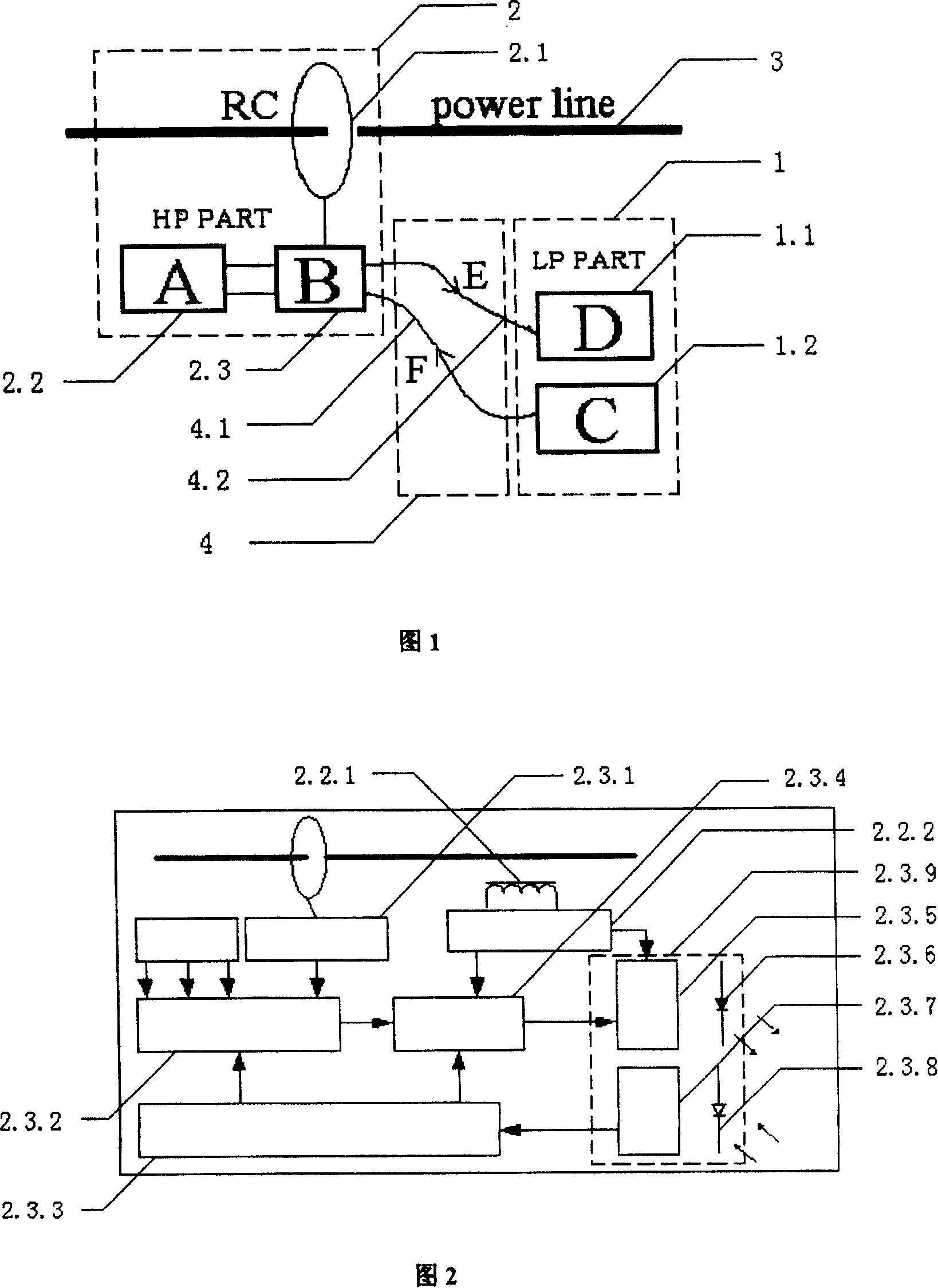
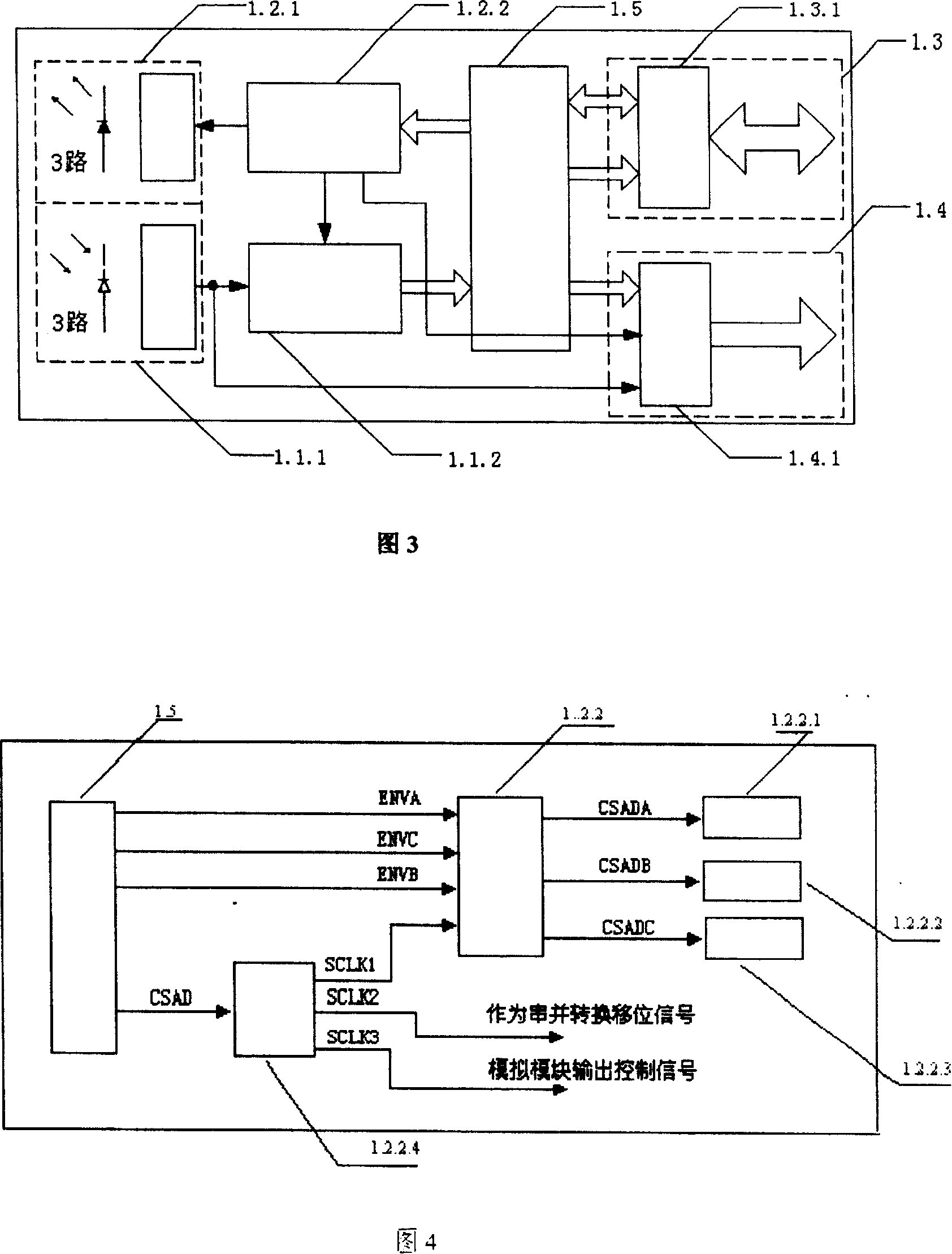
[0026] The high-voltage side data acquisition board (2) is installed on the side of the transmission line (3), and the current sensing element (2.1) on the data acquisition board (2) converts the large current signal on the current-carrying conductor (3) into a small voltage signal for output , transmitted to the ADC (2.3.4) through the signal conditioning circuit (2.3.1), each ADC samples the analog signal at the same time under the control timing transmitted by the control fiber (4.1) (the control timing is determined by the low-voltage side circuit (1) Generated by the waveform logic unit (1.2.2), convert it into a digital signal and drive the light-emitting diode (2.3.6) to emit light through the drive circuit (2.3.5), and the light signal output by the LED is transmitted to the low-voltage side through the optical fiber (4.2) circuit, t...


PUM


Abstract

The synchronously sampling multiphase digital photoelectric current mutual inductor consists of several high voltage side circuits, several transmitting fibers and one low voltage side circuit. The basic characteristics of the digital photoelectric current mutual inductor include the control of several phase circuit sampling in the high voltage side by the clock from the low voltage side, the hardware implementation of the simultaneous sampling of the three phase, A, B and C, current, the simultaneous sampling based on the united clock GPS and software quasi-synchronous sampling tracking power network frequency, and the simple combination of photoelectric current / voltage measurement. The present invention can raise the measurement precision of current in power system and optimize the interface performance of secondary output to accommodate the development of digital, microcomputerized and intelligent electric power measurement and protection.

Description

(1) Technical field [0001] The invention belongs to the field of power system measurement, in particular to a digital electronic current measuring device combined with photoelectricity. (2) Technical background [0002] Conventional CTs have been used to measure current in power systems for over a hundred years. It provides input signals for the metering, relay protection, control and monitoring of the power system, which is of great significance. With the increasing power capacity and higher voltage level transmitted by the power system, conventional CT has insurmountable problems due to its sensing mechanism: (1) The insulation technology requirements are complex, bulky and heavy, and the cost is high; (2) The saturation of the transformer iron core under the fault state limits the transient response speed and accuracy of the CT; (3) Due to the influence of the magnetic saturation of the iron core and the hysteresis loop, the transient output current of the CT is seriousl...

Claims


Application Information

Patent Timeline
Patent Type & Authority Patents(China)
IPC IPC(8): G01R19/25G01R19/00
Inventor 陈允平刘会金王群峰
Owner WUHAN UNIV
Why Eureka
Try Eureka