
Band gap voltage reference source

A technology of voltage reference source and reference circuit, which is applied in the electronic field to achieve the effect of small temperature coefficient

Inactive Publication Date: 2012-02-15
UNIV OF ELECTRONICS SCI & TECH OF CHINA
View PDF5 Cites 31 Cited by
  • Summary
  • Abstract
  • Description
  • Claims
  • Application Information

AI Technical Summary

Problems solved by technology

[0008] The purpose of the present invention is to solve the problems existing in the existing first-order compensation bandgap voltage reference source, and propose a bandgap voltage reference source

Method used


Image

  • Band gap voltage reference source
  • Band gap voltage reference source
  • Band gap voltage reference source

Examples


Embodiment Construction

[0027] The present invention will be further elaborated below in conjunction with the accompanying drawings and specific embodiments.

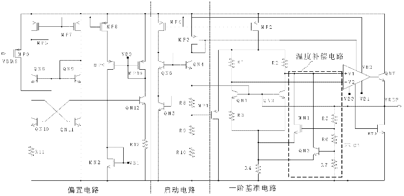
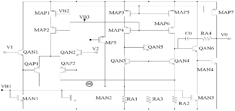
[0028] The bandgap voltage reference source of the present invention is as figure 2 As shown, it includes: a bias circuit, a start-up circuit, a first-order reference circuit, a temperature compensation circuit and an error amplifier circuit, wherein the bias circuit provides a bias voltage for the bandgap voltage reference source, and the The start-up circuit is used to make the first-order reference circuit work normally, the first-order reference circuit generates a reference voltage with a low temperature coefficient, the temperature compensation circuit is used for temperature compensation of the first-order reference circuit, and the error amplifier circuit is used for Stabilize the operating point of the first-order reference circuit.

[0029] Here, the first-order reference circuit includes a first NPN transistor QN1, a second NPN tr...


PUM


Abstract

The invention discloses a band gap voltage reference source. The band gap voltage reference source comprises a biasing circuit, a start circuit and a first-order reference circuit, and is characterized by also comprising a temperature compensation circuit and an error amplifier circuit, wherein the temperature compensation circuit comprises an NPN transistor, a first N-channel metal oxide semiconductor (NMOS) transistor, a fifth resistor, a sixth resistor and a seventh resistor. In the band gap voltage reference source provided by the invention, temperature compensation is realized, namely a reference voltage is obtained by adding a collector current and the drain current of a metal oxide semiconductor (MOS) transistor in a sub-threshold region of a bipolar device into a conventional first-order temperature compensation band gap reference circuit, so that an output reference voltage has a smaller temperature coefficient.

Description

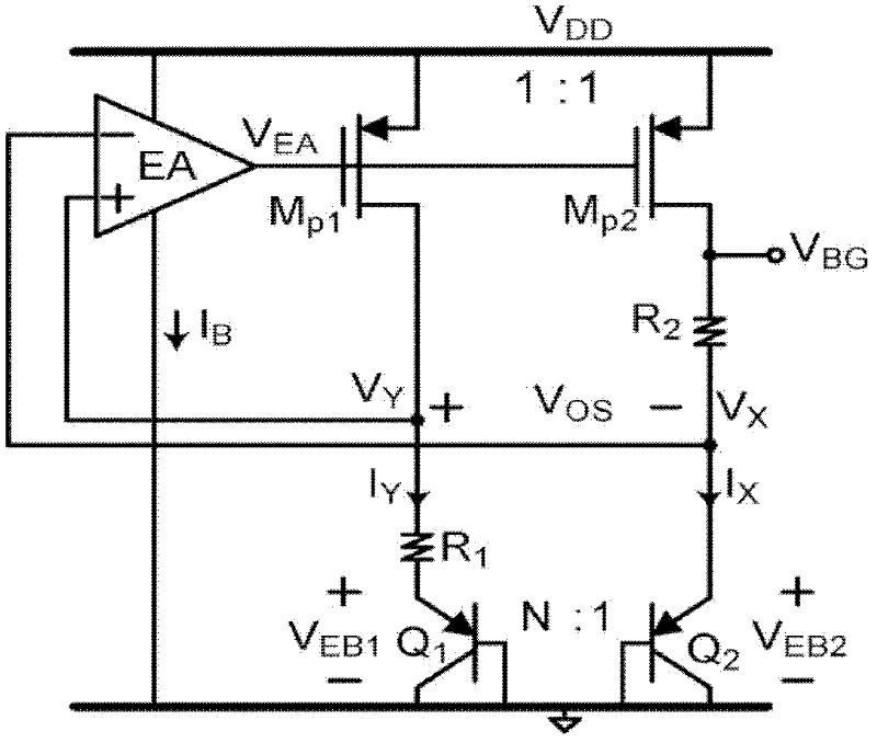
technical field [0001] The invention belongs to the technical field of electronics, and in particular relates to the design of a voltage reference source (Voltage Reference). Background technique [0002] Voltage reference sources are widely used in various analog and digital-analog hybrid integrated circuits such as oscillators, phase-locked loops (PLL, Phase Locked Loop) and data converters. Their temperature coefficient (TC, Temperature Coefficient) and power supply rejection ratio (PSRR) , Power Supply Rejection Ratio) largely determines the pros and cons of system performance. [0003] traditional V-based BE and thermal voltage V T Mutually compensated bandgap voltage reference sources are widely used, such as figure 1 As shown, due to the clamping effect of the error amplifier, making V X with V Y The voltages at the two points are basically equal, that is, V X =V Y =V BE2 , at the same time, the currents in the two circuits are also equal, then: ...

Claims


Application Information

Patent Timeline
Patent Type & Authority Applications(China)
IPC IPC(8): G05F1/567
Inventor 周泽坤王会影石跃蔡小祥鲍小亮王易明鑫张波
Owner UNIV OF ELECTRONICS SCI & TECH OF CHINA
Learn More