Stamping die for automobile clutch diaphragm spring

A diaphragm spring, stamping die technology, applied in forming tools, manufacturing tools, metal processing equipment, etc., can solve the problems of difficult product position accuracy, low production efficiency, poor flatness, etc., and achieve good product concentricity and flatness. The effect of good degree and quality improvement

Inactive Publication Date: 2012-02-22
WUHU DAJIE CLUTCH
View PDF4 Cites 5 Cited by
  • Summary
  • Abstract
  • Description
  • Claims
  • Application Information

AI Technical Summary

Problems solved by technology

In the past, the large end of the diaphragm spring was rounded by turning. The special-shaped window was extruded in one window direction and then rotated in a window direction and then extruded the rounded corner. Because the separation index of the diaphragm spring is relatively large and in the circumferential direction It is evenly distributed, so it is time-consuming for workers to operate and it is easy to forget to squeeze less chamfering. After chamfering, the inner bow of the product will cause poor flatness. The most important thing is that the position accuracy of the product is difficult to control and the production efficiency is not high.

Method used


Image

  • Stamping die for automobile clutch diaphragm spring
  • Stamping die for automobile clutch diaphragm spring
  • Stamping die for automobile clutch diaphragm spring

Examples


Embodiment Construction

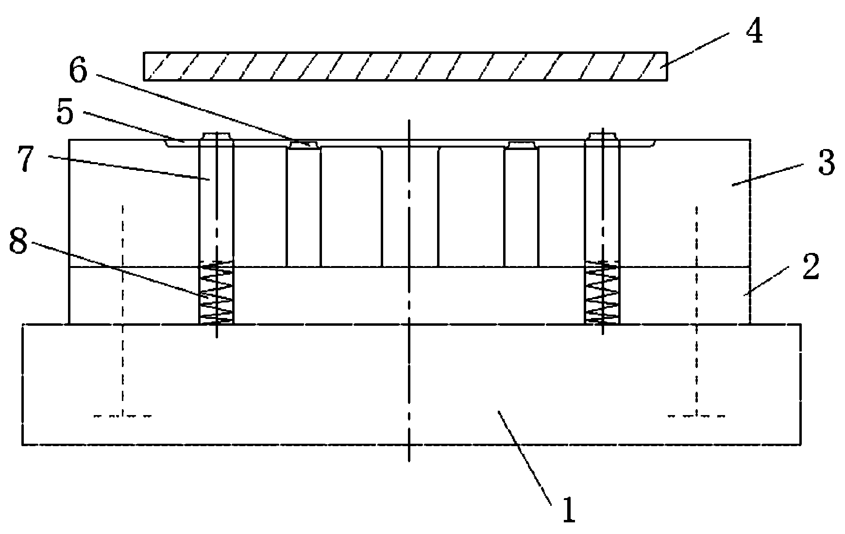
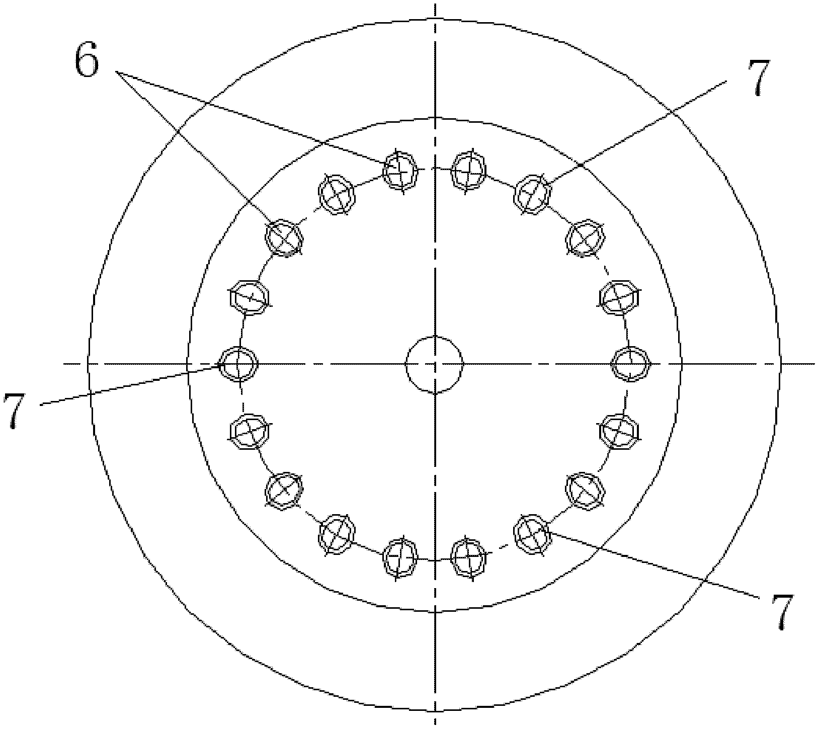
[0016] Such as Figure 1 ~ Figure 3 A stamping die for an automobile clutch diaphragm spring is shown, including a lower template 1, a backing plate 2, a chamfering die 3 and an upper template 4 for pressing down. On the upper end surface of the template 1, the chamfering die 3 is connected to the upper end face of the backing plate 2, the upper end face of the chamfering die 3 is provided with a groove 5 for placing a diaphragm spring, and the chamfering die 3 is provided with A plurality of chamfering punches 6, the top of the chamfering punches 6 is arranged in the groove 5, the chamfering die 3 is provided with a positioning pin 7, the top position of the positioning pins 7 is higher than the chamfering punch 6, The top of the positioning pin 7 is provided with a chamferable punch, the bottom of the positioning pin 7 is connected with one end of the spring 8, and the other end of the spring 8 passes through the backing plate 2 and is connected to the upper end surface of t...


PUM


Abstract

The invention discloses a stamping die for an automobile clutch diaphragm spring, which comprises a lower die plate, a padding plate, a chamfering female die and a pressing-down upper die plate, wherein the padding plate is connected on the upper end surface of the lower die plate, the chamfering female die is connected on the upper end surface of the padding plate, a groove for placing the diaphragm spring is arranged on the upper end surface of the chamfering female die, a plurality of chamfering punches are arranged on the chamfering female die, the top ends of the chamfering punches are arranged in the groove, a positioning pin is arranged on the chamfering female die, the position at the top of the positioning pin is higher than the chamfering punches, a punch which can be chamfered is arranged at the top of the positioning pin, the bottom of the positioning pin is connected with one end of the spring, and the other end of the spring penetrates through the padding plate and is connected on the upper end surface of the lower die plate. The stamping die has the following advantages: 1) the chamfered part of a diaphragm are uniform and smooth, the planeness of a product is good,the machining process step is saved, the concentricity of the product is good and the production efficiency is improved; and 2) after chamfering is completed in one process step, the position precision of a special-shaped hole is high, the quality of the product is improved and the cost is saved.

Description

technical field [0001] The invention relates to the technical field of automobile clutches, in particular to a stamping die for an automobile clutch diaphragm spring. Background technique [0002] The clutch is an important part directly connected with the engine in the automobile transmission system, and the diaphragm spring is an important part in the clutch assembly. The large end side of the diaphragm spring is extruded rounded corner and the extruded rounded corner at the special-shaped window is to prevent the stress concentration of the diaphragm spring during heat treatment and normal use, and effectively prevent the force value of the diaphragm spring from attenuating or breaking. In the past, the large end of the diaphragm spring was rounded by turning. The special-shaped window was extruded in one window direction and then rotated in a window direction and then extruded the rounded corner. Because the separation index of the diaphragm spring is relatively large an...

Claims


Application Information

Patent Timeline
Patent Type & Authority Applications(China)
IPC IPC(8): B21D37/10
Inventor 田瑞夏文瀚董相谋丁天峰江志宏吴勇建
Owner WUHU DAJIE CLUTCH
Why Eureka
Try Eureka