Vacuumized nitrogen filling and plugging device

A plugging device and vacuuming technology, applied in the fields of medical packaging machinery and food, can solve the problems of falling into the bottle body, contamination of medicinal liquid, complicated structure of the plugging mechanism, etc. Effect

Active Publication Date: 2012-02-22
TRUKING TECH LTD
View PDF6 Cites 7 Cited by
  • Summary
  • Abstract
  • Description
  • Claims
  • Application Information

AI Technical Summary

Problems solved by technology

For example, a Chinese patent application number 201020277062.4 discloses a vacuum pumping and nitrogen filling stoppering device. The stopper removal mechanism has a complex structure, and the stopper is removed by clamping from the side of the stopper. The lateral dimension of the stopper removal mechanism is larger than the diameter of the stopper. ; and because the bottle body of the bottle body needs to be in contact with the sealing sleeve at the bottom of the connecting sleeve for sealing, it should be ensured that the inner diameter of the sealing sleeve is smaller than the diameter of the bottle body of the bottle body. Will not be able to pass through the gland for plug removal due to lateral dimension too large
Furthermore, before the bottle body and the sealing sleeve contact and seal, the bottle body is in an open state all the time, and the particles generated by the contact between the sealing sleeve and the bottle mouth and the particles generated by the mutual movement between the mechanisms may fall into the bottle body during contact sealing. Pollution caused by liquid medicine in the bottle

Method used


Image

  • Vacuumized nitrogen filling and plugging device
  • Vacuumized nitrogen filling and plugging device
  • Vacuumized nitrogen filling and plugging device

Examples


Embodiment Construction

[0023] The present invention will be described in further detail below in conjunction with the accompanying drawings and specific embodiments.

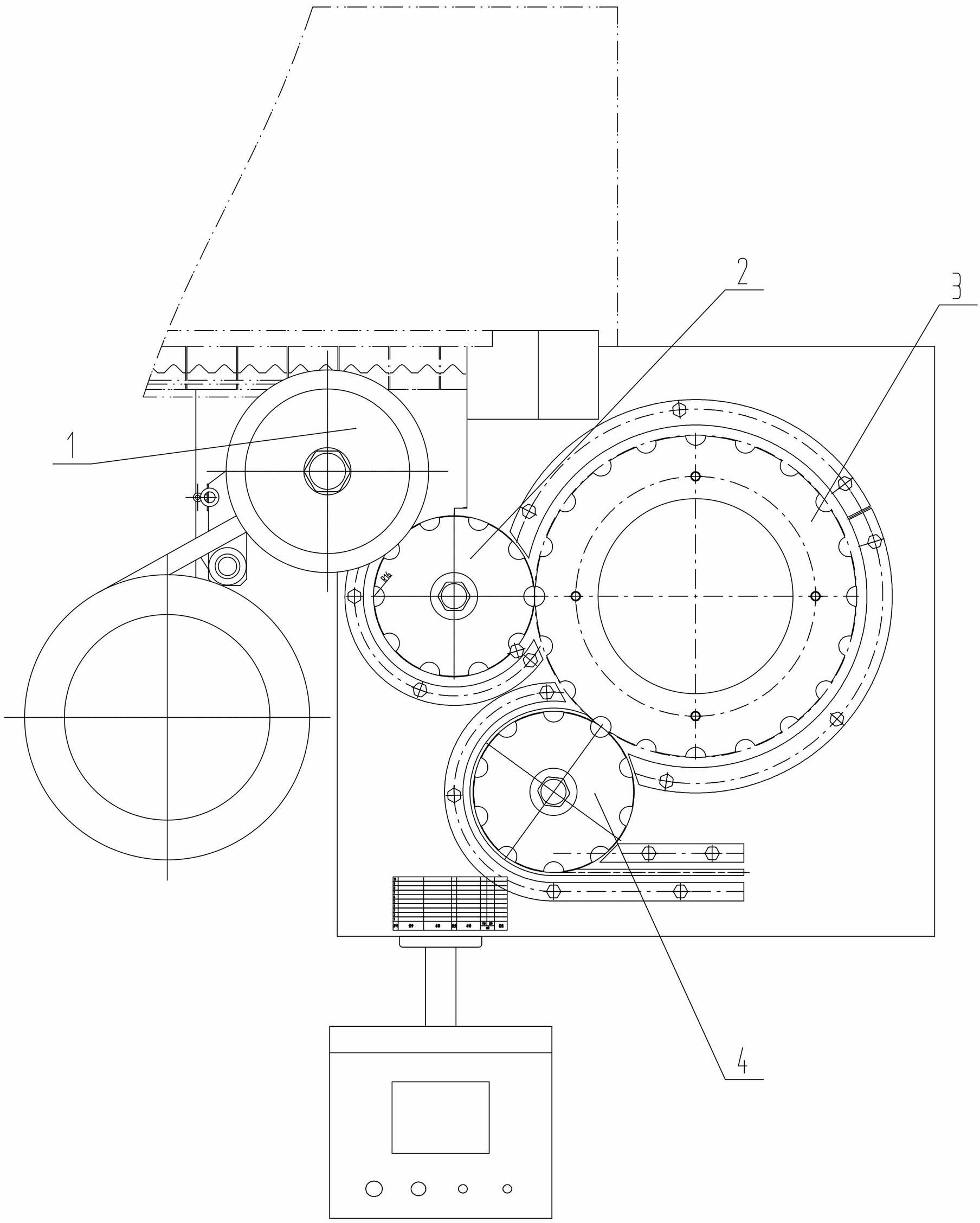
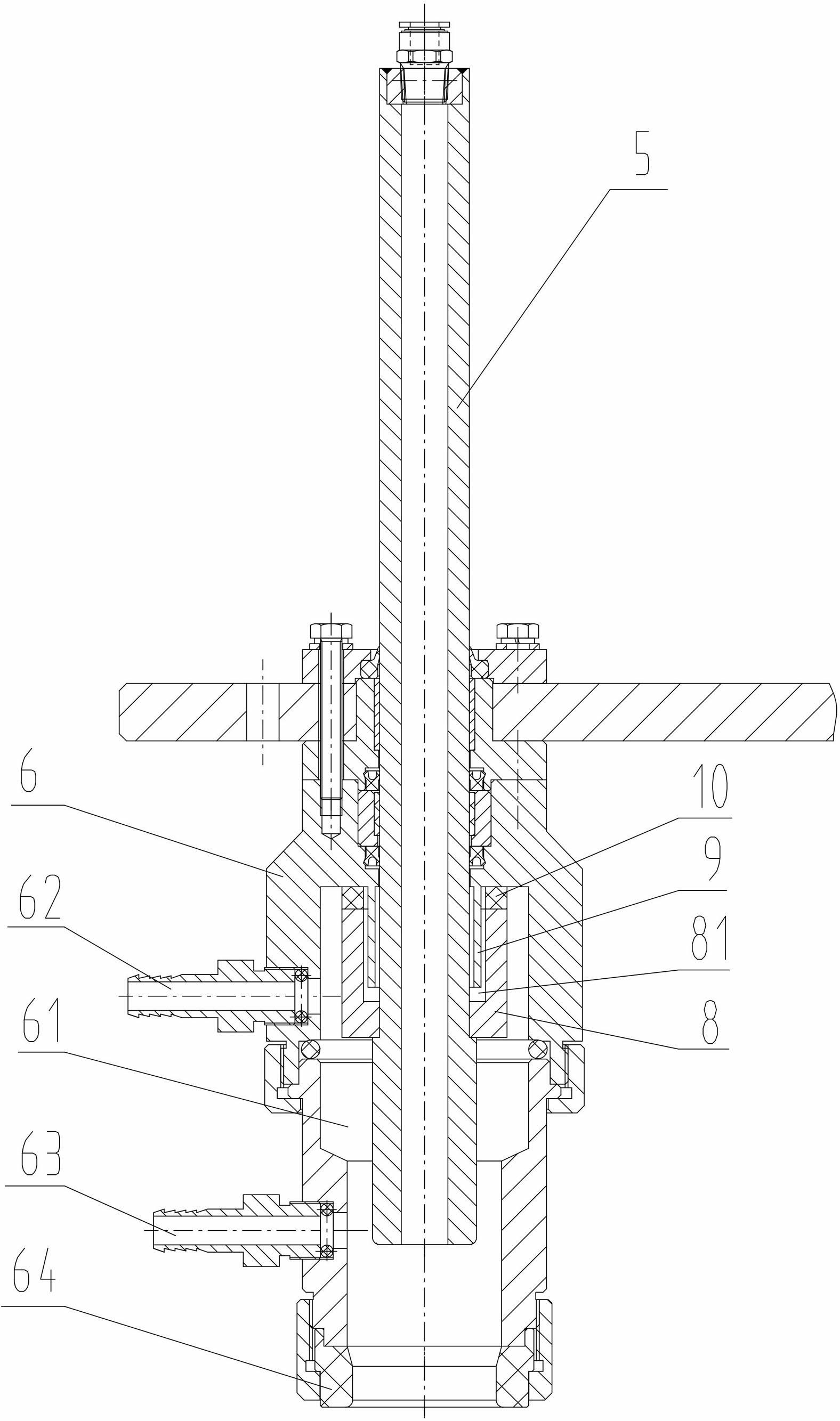
[0024] like figure 1 , figure 2 As shown, the vacuum-pumping and nitrogen-filling plugging device of the present invention includes a plugging part 1 and a vacuum-pumping and nitrogen-filling part 3. After the stoppering is completed, it is transferred to the vacuum pumping and nitrogen filling part 3 by the transition dial assembly 2. Vacuumizing and nitrogen filling part 3 includes lifting shaft 5 with vacuum adsorption function and connecting sleeve 6 provided with vacuuming and nitrogen filling chamber 61. Of course, lifting shaft 5 can also be composed of multiple sections to ensure that the lower adsorption end is suitable for glue. Plug shape and size. The lifting shaft 5 is socketed with the connecting sleeve 6, and the lower part of the lifting shaft 5 is placed in a vacuum-pumped nitrogen-filled chamber 61. The vacuum a...


PUM


Abstract

The invention discloses a vacuumized nitrogen filling and plugging device, which comprises a plugging part and a vacuumized nitrogen filling part, wherein the plugging part is connected with the vacuumized nitrogen filling part through a transition shifting wheel component; the vacuumized nitrogen filling part comprises a lifting shaft with a vacuum absorption function, and a connecting sleeve with a vacuumized nitrogen filling cavity; the lifting shaft is sleeved with the connecting sleeve; and the lower part of the lifting shaft is arranged into the vacuumized nitrogen filling cavity. The vacuumized nitrogen filling and plugging device has a simple structure and a wide applicability range and can reduce the pollution risk during plugging.

Description

technical field [0001] The invention mainly relates to the field of food and medicine packaging machinery, in particular to a vacuum-pumping, nitrogen-filling and stoppering device. Background technique [0002] In the field of food and medicine packaging machinery, vacuum pumping, nitrogen filling and stoppering devices have been widely used. Commonly used vacuum nitrogen filling plugging devices generally integrate the plugging function on the vacuum nitrogen filling part, so a plug removal mechanism must be installed at the lower end of the lifting shaft of the vacuum nitrogen filling part to remove the plug from the upper plug part. For example, a Chinese patent application number 201020277062.4 discloses a vacuum pumping and nitrogen filling stoppering device. The stopper removal mechanism has a complex structure, and the stopper is removed by clamping from the side of the stopper. The lateral dimension of the stopper removal mechanism is larger than the diameter of the...

Claims


Application Information

Patent Timeline
IPC IPC(8): B65B7/28B65B31/04
Inventor 龙煌辉李新华阳文录唐岳
Owner TRUKING TECH LTD
Why Eureka
Try Eureka