Circular self-seepage recharge well head assembly

A technology of wellhead device and recharge well, which is applied in water supply installations, drinking water installations, water conservancy projects, etc., can solve the problems of large construction volume, concrete manhole cover affecting recharge volume, consumption of large building materials, etc. The effect of cross-sectional area, prevention of low water level sewage recharge, and saving of sand and gravel building materials

Inactive Publication Date: 2012-02-22
UNIV OF JINAN
View PDF5 Cites 14 Cited by
  • Summary
  • Abstract
  • Description
  • Claims
  • Application Information

AI Technical Summary

Problems solved by technology

However, the problems of this self-seepage-recharge well are: 1. The self-seepage-recharge well is placed at the bottom of the river or the bottom of the canal, which is very easy to be silted up and washed away by the water flow, which affects the service life; 2. The recharge tank is buried in Underground, there is only a free water inlet section on the top of the recharge tank. In order to ensure sufficient recharge volume, the recharge tank requires a large cross-sectional area and a large amount of construction; 3. To build an ordinary recharge tank requires backfilling 10m 3 Left and right sand and gravel consume a lot of building materials; 4. The use of concrete manhole covers affects the amount of recharge
These defects have seriously affected the use effect of the recharge well, and did not maximize its water retention efficiency

Method used


Image

  • Circular self-seepage recharge well head assembly
  • Circular self-seepage recharge well head assembly
  • Circular self-seepage recharge well head assembly

Examples


Embodiment Construction

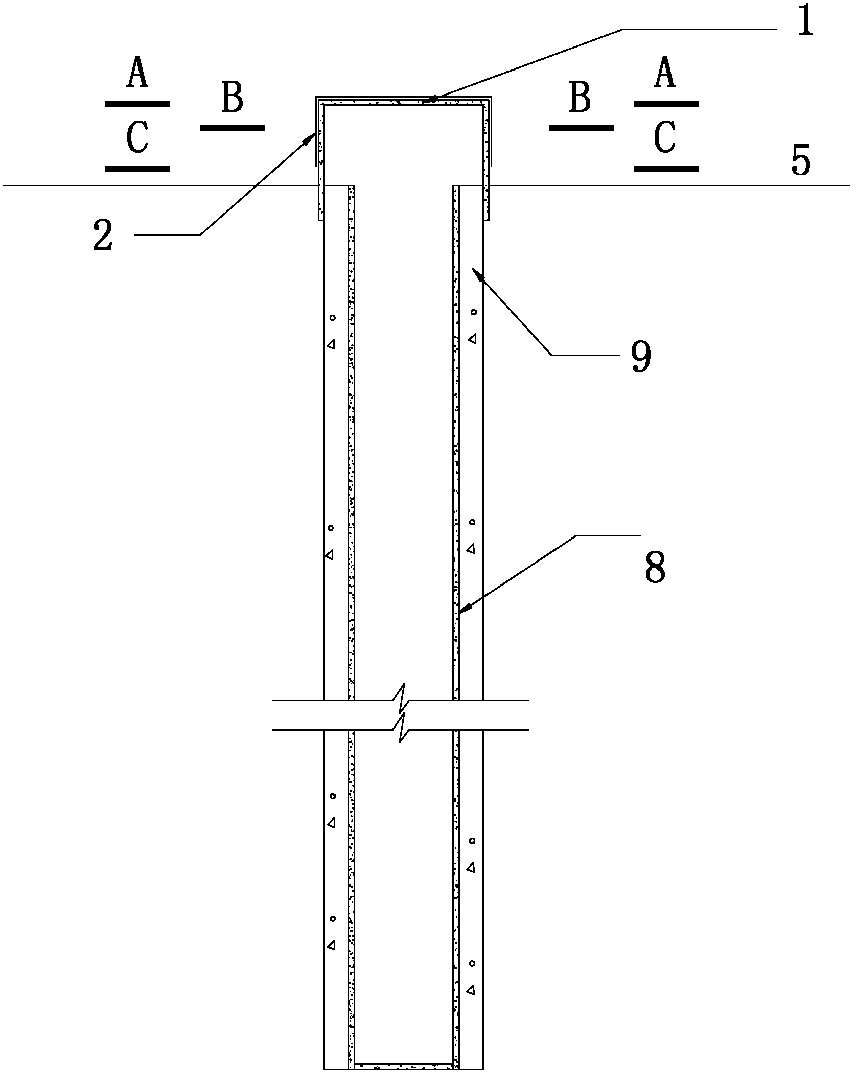
[0023] exist figure 1 Among them, this kind of circular self-seepage recharge well head device involves recharge well 8 and its wellhead. The recharge well 8 is located below the bottom of the river or the bottom of the canal. A cover is provided on the recharge well 8. The wellhead device above, the wellhead device includes a circular bottomless well cover 1, and a geotextile filter layer 2 fixedly arranged on the outside of the well cover; the well cover 1 is made of reinforced concrete or concrete or masonry material or hard chemical Any of the materials of construction. The geotextile filter layer 2 is composed of geotextiles with filter functions; the geotextiles are woven geotextiles or non-woven geotextiles. The geotextile filter layer is flatly laid on the top cover and the outside of the side wall of the manhole cover, and fixed on the manhole cover. The top cover is made into a horizontal plane or an inclined surface with a gradient of 1% in the direction of water ...


PUM


Abstract

The invention discloses a circular self-seepage recharge well head assembly, belongs to the technical field of water retention and relates to a recharge well and a well head thereof. The recharge well is positioned below the ground surface of a river bottom or trench bottom. The circular self-seepage recharge well head assembly is characterized in that a well head device covering above the well head is arranged on the recharge well and comprises a circular bottomless well cover and a geotextile reversed filter fixedly arranged on the outer side of the well cover, the well cover comprises a circular top cover and a hollow bottomless column body vertically connected to the side wall on the circumference of the top cover, the lower part of the side wall is positioned below the ground surfaceof the river bottom or trench bottom, a top cover square hole is arranged on the top cover, the side wall is provided with a side wall square hole, the recharge well is positioned at the middle of the bottom of the well head device, and gravel reversed filter materials are backfilled around the recharge well. The circular self-seepage recharge well head assembly has strong self-recharge capacity,the function of preventing low-water-level sewage from being backfilled, the function of reversed filtering and certain silt-preventing and impact-resisting capacities, is easy to construct and ensures that the gravel reversed filter materials can be saved.

Description

technical field [0001] The invention relates to a self-seepage recharge well for pressureless groundwater recharge, in particular to a circular self-seepage recharge well head device, which belongs to the technical field of water conservation. Background technique [0002] How to preserve water in some water-deficient areas or how to prevent seawater backflow caused by excessive exploitation of groundwater in coastal areas is a major issue that restricts local people's life and economic development. The means to solve this issue are to strengthen people's awareness of water conservation. Effective use of rain and flood resources is also one of the important measures. [0003] In order to make full use of rain and flood resources, in seasonal rivers with no pollution or slight pollution, a kind of recharge well with the function of filtering particulate impurities in water is often arranged, that is, self-infiltration recharge well, also known as reverse filter recharge well ...

Claims


Application Information

Patent Timeline
Patent Type & Authority Applications(China)
IPC IPC(8): E03B3/34E02D29/09
Inventor 李旺林李英特
Owner UNIV OF JINAN
Why Eureka
Try Eureka