Differential pressure type airspeed sensor testing system

A technology of airspeed sensor and test system, which is applied in the test/calibration of speed/acceleration/shock measurement equipment, speed/acceleration/shock measurement, instruments, etc., and can solve the problems of airspeed sensor testing and correction, air velocity and Difficult to control the direction, limited dynamic range of test speed, etc., to achieve the effect of increasing dynamic range and accuracy, low operation and maintenance costs, and low cost

Active Publication Date: 2012-02-22
INST OF AUTOMATION CHINESE ACAD OF SCI
View PDF4 Cites 14 Cited by
  • Summary
  • Abstract
  • Description
  • Claims
  • Application Information

AI Technical Summary

Problems solved by technology

The main defects of the above three methods are: ①The main defect of the simulated airflow method is that it is difficult to control the speed and direction of the airflow; ②The on-board test method involves many aspects, and it is difficult to implement; When driving on the ground, ground effect turbulence is likely to interfere with the airspeed
[0004] In addition, the applicant realized that the prior art differential pressure airspeed sensor test method also has the following technical defects: the dynamic range of the test speed is limited, the test speed is uneven, and the direction error of the test speed is large, which leads to the test of the airspeed sensor and Correction has a large impact

Method used


Image

  • Differential pressure type airspeed sensor testing system
  • Differential pressure type airspeed sensor testing system
  • Differential pressure type airspeed sensor testing system

Examples


Embodiment Construction

[0032] In order to make the object, technical solution and advantages of the present invention clearer, the present invention will be described in further detail below in conjunction with specific embodiments and with reference to the accompanying drawings.

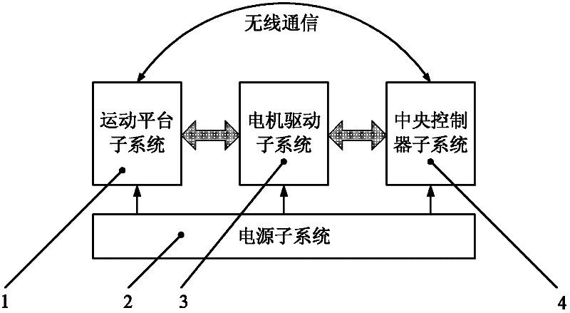
[0033] figure 1 It is the overall structure diagram of the differential pressure airspeed sensor testing system of the embodiment of the present invention. Such as figure 1 As shown, the system includes four parts: motion platform subsystem 1, power supply subsystem 2, motor drive subsystem 3, and central controller subsystem 4. Its working principle can be briefly described as: the central controller subsystem 4 sends motion control instructions to the motor drive subsystem 3, and the motor drive subsystem 3 realizes the speed control of the motion platform subsystem 1 according to the instructions, so that the differential pressure air The two sides of the speed sensor 1111 generate a differential pressure, and the di...


PUM


Abstract

The invention discloses a differential pressure type airspeed sensor testing system. The system comprises a motion platform subsystem 1, a power supply subsystem 2, a motor driving subsystem 3 and a central controller subsystem 4. In the operation principle of the system, the central controller subsystem 4 is used for transmitting a motion control command to the motor driving subsystem 3, and themotor driving subsystem 3 is used for controlling the rotating speed of the motion platform subsystem 1 according to the command, so that differential pressure is generated on the two sides of a differential pressure type airspeed sensor 1111 and is converted into a voltage signal through the differential pressure type airspeed sensor 1111, and the voltage signal is processed by a signal conditioning / acquiring unit and a micro-processing unit and then is transmitted to the central controller subsystem 4 through a first wireless communication interface unit 1114 to finish testing and calibration. By the differential pressure type airspeed sensor testing system, the dynamic range of a test speed can be enlarged, the uniformity of the test speed can be improved, and the direction errors of the test speed can be reduced.

Description

technical field [0001] The invention relates to the technical field of electrical measurement in the electronics industry, in particular to a differential pressure airspeed sensor testing system. Background technique [0002] Airspeed refers to the speed of the aircraft relative to the air, and is an important atmospheric parameter that needs to be measured during the flight of the aircraft. Since the lift of an aircraft is proportional to the dynamic pressure, and the dynamic pressure is proportional to the square of the airspeed, airspeed measurement is a very important task whether the aircraft is cruising at a specified altitude or during takeoff and landing . Generally speaking, the airspeed measurement is realized by the airspeed sensor. With the rapid development of semiconductor technology, the monolithic integrated silicon strain gauge differential pressure sensor is getting smaller and smaller, with higher precision and lower cost, and its performance is fully ca...

Claims


Application Information

Patent Timeline
IPC IPC(8): G01P21/02
Inventor 谭湘敏范国梁易建强
Owner INST OF AUTOMATION CHINESE ACAD OF SCI
Why Eureka
Try Eureka