Foil winding coil mold for multiple copper bar outgoing lines
A mold and coil technology, used in coil manufacturing, electrical components, inductor/transformer/magnet manufacturing, etc., can solve the problems of low production efficiency, uneven arrangement of copper bars, and unsightly appearance, and achieve high production efficiency, neat arrangement, good practical effect
- Summary
- Abstract
- Description
- Claims
- Application Information
AI Technical Summary
Problems solved by technology
Method used
Image

Examples
Embodiment 1
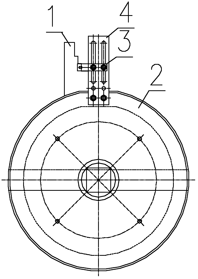
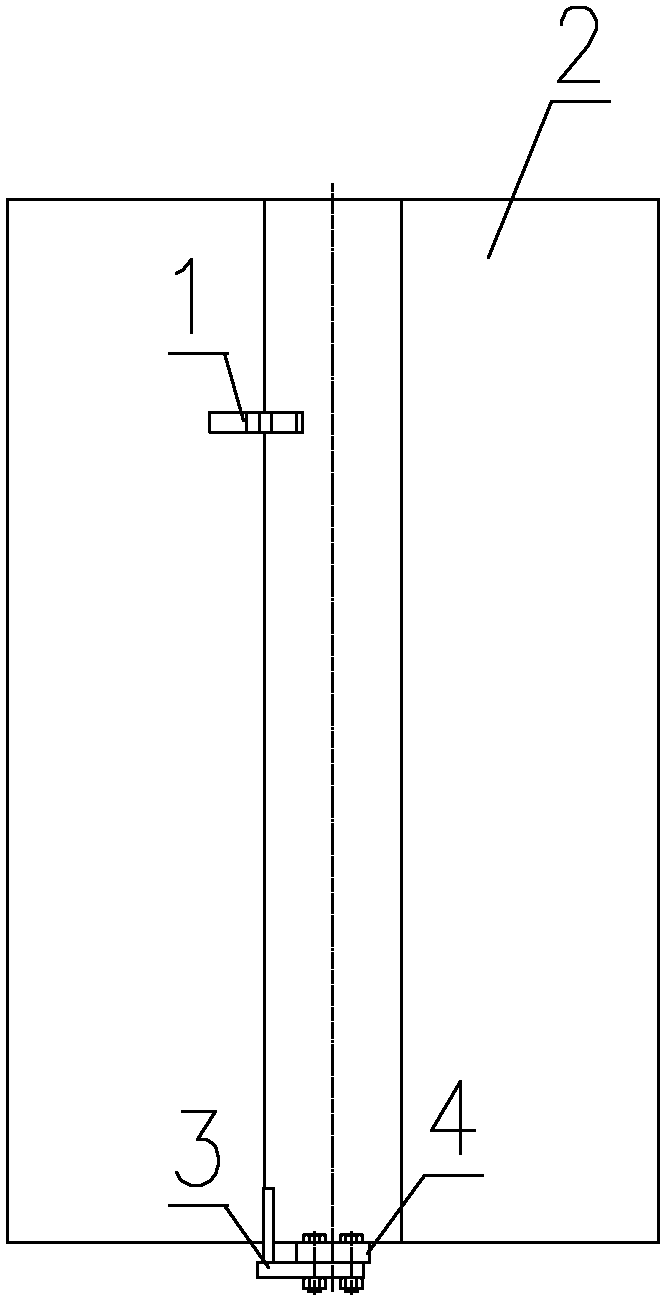
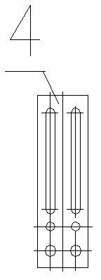
[0024] A foil wound coil die for multiple copper discharge wires including end plates, support plates and die roll. The upper end of the steel plate rolling cylinder 2 for the mold foil winding coil is fixed with a copper bar upper end outlet baffle plate 1; the lower end has a hole, and an outlet fixing plate 4 is fixed. Fixing block 3 for the outgoing line at the lower end of the row.
[0025] The slot holes of the lower end of the steel plate rolling drum for the outlet fixing plate are 2 elongated through holes. The outgoing wire fixing block at the lower end of the copper bar is an L-shaped structure, and is fixed on the outgoing wire fixing block by bolts. The outlet baffle plate at the upper end of the copper bar is welded on the steel drum.
[0026] The winding process of this embodiment:
[0027] Refer to attached Figure 1 to Figure 5 .
[0028] During winding, the mold is installed on the threading bar of the foil winding machine, the outlet baffle plate 1 at t...
PUM
 Abstract
Description
Claims
Application Information