Hybrid type working machine

A working machine, hybrid technology, applied in mechanical equipment, hybrid vehicles, motor vehicles, etc., can solve problems such as stopping the engine, excessive engine load, etc., and achieve the effect of suppressing overload

Inactive Publication Date: 2012-02-22
SUMITOMO HEAVY IND LTD
View PDF4 Cites 2 Cited by
  • Summary
  • Abstract
  • Description
  • Claims
  • Application Information

AI Technical Summary

Problems solved by technology

Therefore, as an engine that obtains an output corresponding to the current rotation speed in this state, if the auxiliary output of the motor generator is suppressed (or the engine output is used to generate electricity), the load on the engine becomes excessive, and the engine may stop. engine

Method used


Image

  • Hybrid type working machine
  • Hybrid type working machine
  • Hybrid type working machine

Examples


no. 1 Embodiment approach

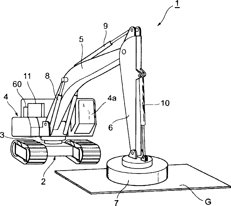
[0033] figure 1 It is a perspective view showing the appearance of a hybrid construction machine 1 as an example of a hybrid machine tool according to the present invention. Such as figure 1 As shown, the hybrid construction machine 1 is a so-called lifting magnet vehicle, and includes a traveling mechanism 2 including crawlers and a revolving body 4 rotatably mounted on the upper portion of the traveling mechanism 2 via a revolving mechanism 3 . The rotating body 4 is equipped with a boom 5 , an arm 6 whose connecting rod is connected to the front end of the boom 5 , and a lifting magnet 7 whose connecting rod is connected to the front end of the arm 6 . The lifting magnet 7 is a device for absorbing and grasping hanging objects G such as steel materials by magnetic force. Boom 5 , stick 6 and lifting magnet 7 are hydraulically driven through boom cylinder 8 , stick cylinder 9 and bucket cylinder 10 respectively. Further, the revolving body 4 is provided with a power sourc...

no. 2 Embodiment approach

[0068] Here, another subject of the hybrid working machine will be described. Figure 11 (a) shows the output of the engine 11 (graph G31), the output of the motor generator (auxiliary motor) (graph G32), the hydraulic output from the main pump 14 (graph G33), and the rotational speed of the engine 11 (graph G33). G34) Graphs of respective time changes. Figure 11 In (a), the left vertical axis represents output (kW), the right vertical axis represents rotational speed (rpm), and the horizontal axis represents time (second). and, Figure 11 (b) is a graph showing the temporal change of the boost pressure (boost pressure). Figure 11 In (b), the vertical axis represents elevated pressure (kPa), and the horizontal axis represents time (seconds).

[0069] exist Figure 11 (a) and Figure 11In (b), when the time t1 second elapses, a load is applied to the hydraulic system, and the driving force to be supplied to the main pump 14 increases from Pa (kW) to Pb (kW). As a result...


PUM


Abstract

A hybrid type working machine having a supercharger, in which overload to the engine is suppressed. The hybrid type working machine (1) comprises an engine (11); a supercharger (42); a motor generator (12) that generates electricity with the driving force of the engine (11), as well as assist the driving force of the engine (11) with the driving force of itself; an inverter circuit (18A) connected to the motor generator (12); and a nonvolatile memory (31) that stores the correlation between the rotating speed of the engine (11) and the boosting pressure of the supercharger (42), and the upper limit value for the output of the engine (11); and is also provided with a controller (30) that drives the inverter circuit (18A). The controller (30) controls the inverter circuit (18A) so as to have the motor generator (12) assist the driving force when the necessary output exceeds the upper limit value for the output, based on the correlation stored in the nonvolatile memory (31).

Description

technical field [0001] The invention relates to a hybrid working machine. Background technique [0002] Conventionally, a machine tool in which a part of a drive mechanism is motorized has been proposed. This type of working machine includes a hydraulic pump for hydraulically driving movable parts such as a boom, an arm, and a bucket, and an AC motor (motor generator) is connected to an internal combustion engine ( engine), and performs operations of assisting the driving force of the engine and charging the battery with electric power generated by the power generation according to various needs. For example, Patent Document 1 discloses such a hybrid working machine. In the hybrid working machine described in Patent Document 1, the distribution of power output by the motor generator to assist the engine is determined based on the required power of the hydraulic pump, and the power distribution is corrected so that the difference between the target rotation speed of the eng...

Claims


Application Information

Patent Timeline
Patent Type & Authority Applications(China)
IPC IPC(8): H02P9/04F02D29/06B60W10/06B60W10/08B60W20/00E02F9/22
CPCB60K6/48B60W10/06B60W10/08B60W10/30B60W20/00B60W30/1884B60W30/1886B60Y2200/25B60Y2200/41B60Y2200/412B60Y2400/435E02F9/2075E02F9/2217E02F9/2246H02P9/04Y02T10/62E02F9/20H02M7/48B60W20/15
Inventor 川岛宏治柳泽诚
Owner SUMITOMO HEAVY IND LTD
Why Eureka
Try Eureka