Hybrid type working machine
A working machine, hybrid technology, applied in mechanical equipment, hybrid vehicles, motor vehicles, etc., can solve problems such as stopping the engine, excessive engine load, etc., to achieve the effect of suppressing overload
- Summary
- Abstract
- Description
- Claims
- Application Information
AI Technical Summary
Problems solved by technology
Method used
Image
Examples
no. 1 Embodiment approach )
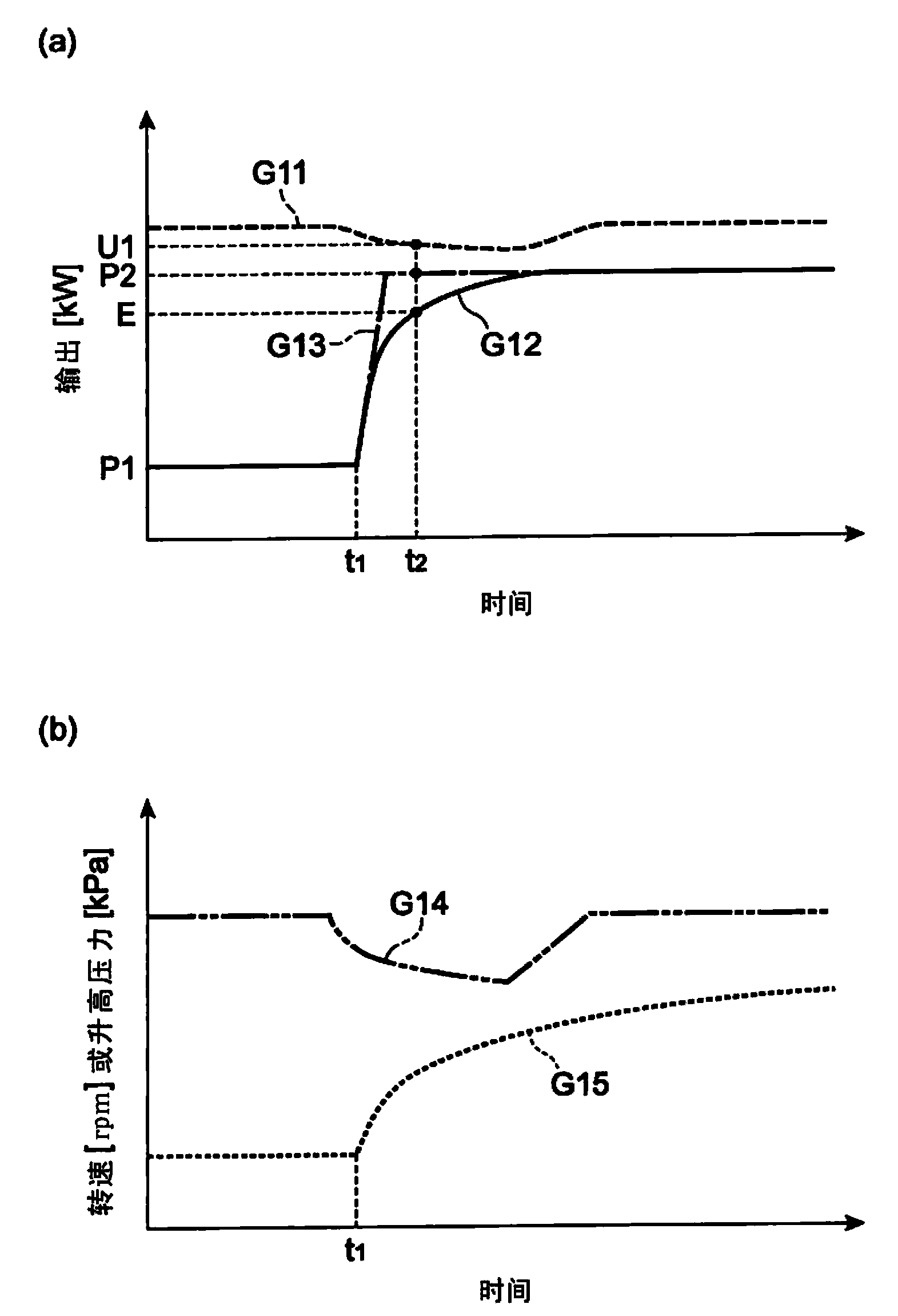
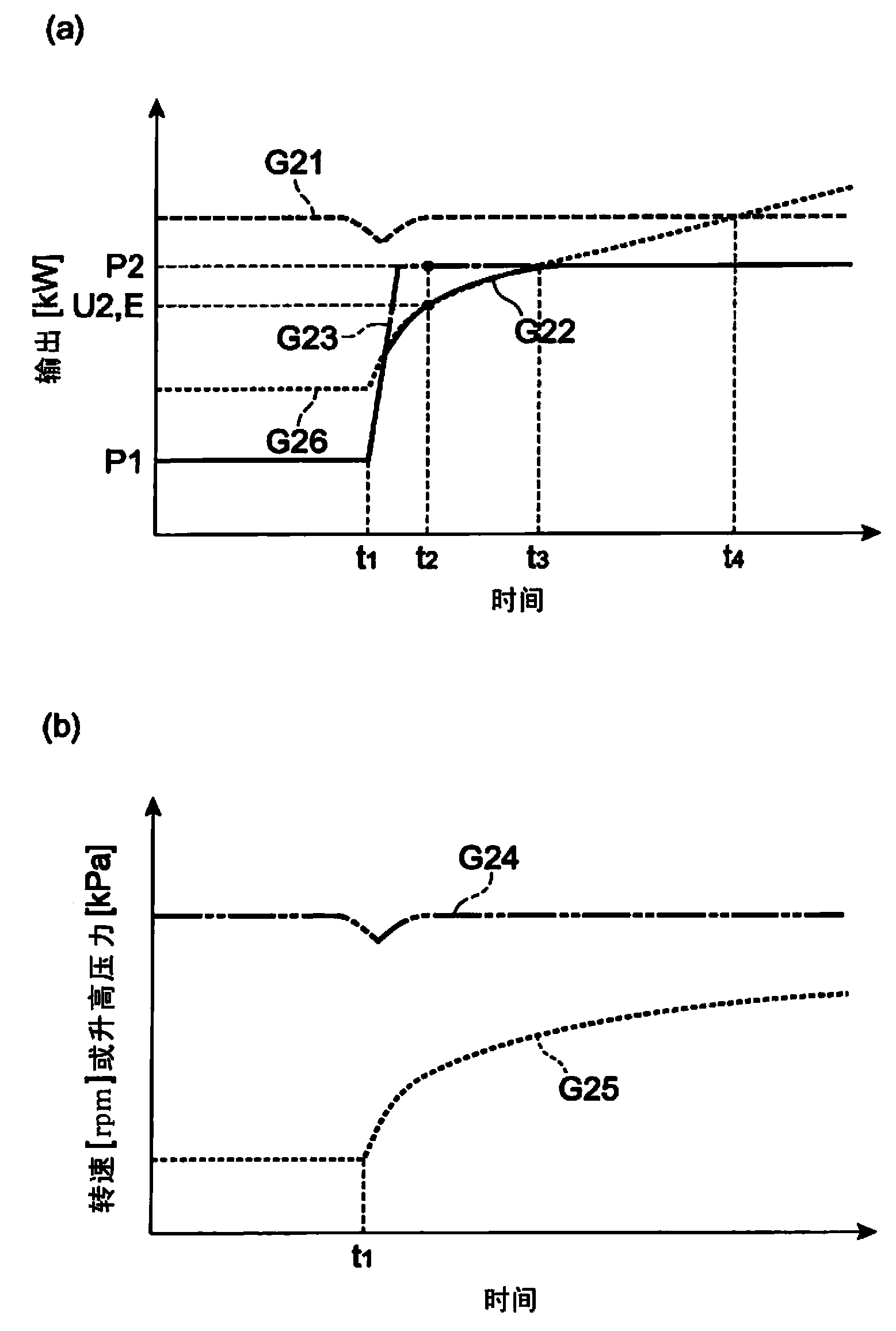
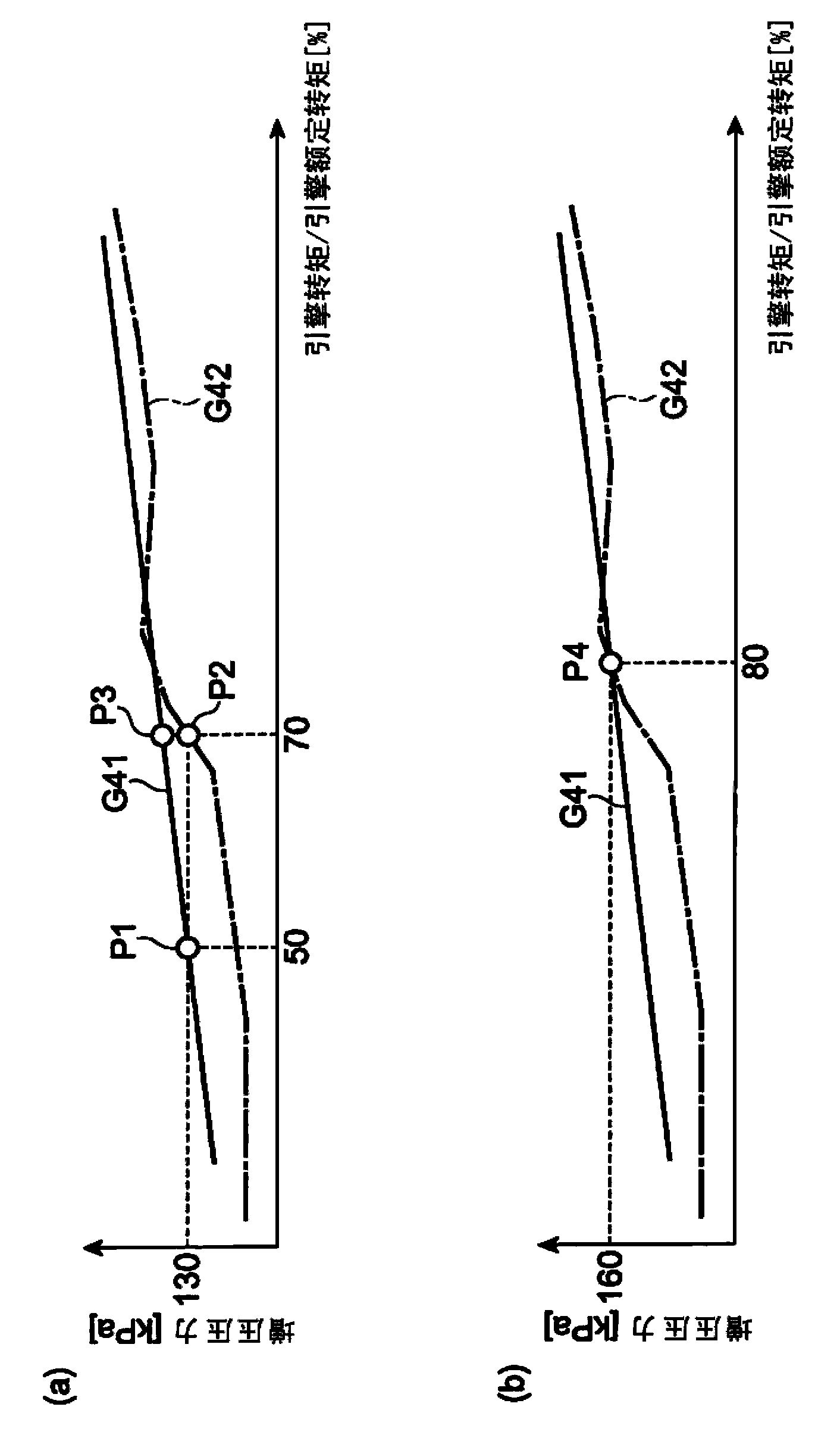
[0033] figure 1 It is a perspective view showing the appearance of a hybrid construction machine 1 as an example of a hybrid machine tool according to the present invention. Such as figure 1 As shown, the hybrid construction machine 1 is a so-called lifting magnet vehicle, and includes a traveling mechanism 2 including crawlers and a revolving body 4 rotatably mounted on the upper portion of the traveling mechanism 2 via a revolving mechanism 3 . The rotating body 4 is equipped with a boom 5 , an arm 6 whose connecting rod is connected to the front end of the boom 5 , and a lifting magnet 7 whose connecting rod is connected to the front end of the arm 6 . The lifting magnet 7 is a device for absorbing and grasping hanging objects G such as steel materials by magnetic force. Boom 5 , stick 6 and lifting magnet 7 are hydraulically driven through boom cylinder 8 , stick cylinder 9 and bucket cylinder 10 respectively. Further, the revolving body 4 is provided with a power sourc...
no. 2 Embodiment approach )
[0068] Here, another subject of the hybrid working machine will be described. Figure 11 (a) shows the output of the engine 11 (graph G31), the output of the motor generator (auxiliary motor) (graph G32), the hydraulic output from the main pump 14 (graph G33), and the rotational speed of the engine 11 (graph G33). G34) graphs of the respective temporal changes. Figure 11 In (a), the left vertical axis represents output (kW), the right vertical axis represents rotational speed (rpm), and the horizontal axis represents time (seconds). and, Figure 11 (b) is a graph showing the time change of the boost pressure (boost pressure). Figure 11 In (b), the vertical axis represents elevated pressure (kPa), and the horizontal axis represents time (second).
[0069] exist Figure 11 (a) and Figure 11In (b), when the time t1 second elapses, a load is applied to the hydraulic system, and the driving force to be supplied to the main pump 14 increases from Pa (kW) to Pb (kW). As a re...
PUM
 Abstract
Description
Claims
Application Information
 - R&D
- Intellectual Property
- Life Sciences
- Materials
- Tech Scout
- Unparalleled Data Quality
- Higher Quality Content
- 60% Fewer Hallucinations
Browse by: Latest US Patents, China's latest patents, Technical Efficacy Thesaurus, Application Domain, Technology Topic, Popular Technical Reports.
© 2025 PatSnap. All rights reserved.Legal|Privacy policy|Modern Slavery Act Transparency Statement|Sitemap|About US| Contact US: help@patsnap.com


