Optical diaphragm and backlight module using same

An optical film, light diffusion technology, applied in optics, optical components, nonlinear optics, etc., can solve the problems of uneven brightness, poor fogging effect, serious hot spot phenomenon, etc.

Inactive Publication Date: 2014-11-26
AU OPTRONICS CORP
View PDF4 Cites 0 Cited by
  • Summary
  • Abstract
  • Description
  • Claims
  • Application Information

AI Technical Summary

Problems solved by technology

[0003] However, light-emitting diodes are point light sources, not linear light sources like traditional cold-cathode tubes. Therefore, the arrangement of light-emitting diodes at intervals will cause the problem of uneven dispersion of light sources, which also causes the phenomenon of hot spots (Hot Spot) in light-emitting diodes. the main cause of
In addition, in order to improve the brightness, the backlight module often places the brightness enhancement film horizontally, but the brightness enhancement film has the effect of image splitting, so the hot spot phenomenon is also indirectly made more serious
Furthermore, under the trend of cost reduction and material integration, the backlight module often integrates the upper diffusion sheet and the brightness enhancement film into a composite film, which also indirectly causes the fogging effect to deteriorate, and also makes the problem of hot spots gradually worsen. Serious, it also causes the user to easily observe the phenomenon of uneven brightness and darkness
Although the liquid crystal display can enlarge the plastic frame in order to cover the hot spot, but this method will cause the display area to become smaller, or the size of the panel module will become larger

Method used


Image

  • Optical diaphragm and backlight module using same
  • Optical diaphragm and backlight module using same
  • Optical diaphragm and backlight module using same

Examples


Embodiment Construction

[0070] A number of embodiments of the present invention will be disclosed in the following drawings. For the sake of clarity, many practical details will be described together in the following description. It should be understood, however, that these practical details should not be used to limit the invention. That is, in some embodiments of the present invention, these practical details are unnecessary. In addition, for the sake of simplifying the drawings, some well-known and commonly used structures and elements will be shown in a simple and schematic manner in the drawings.

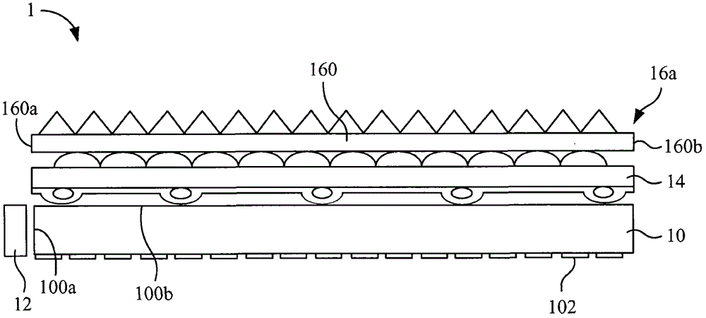
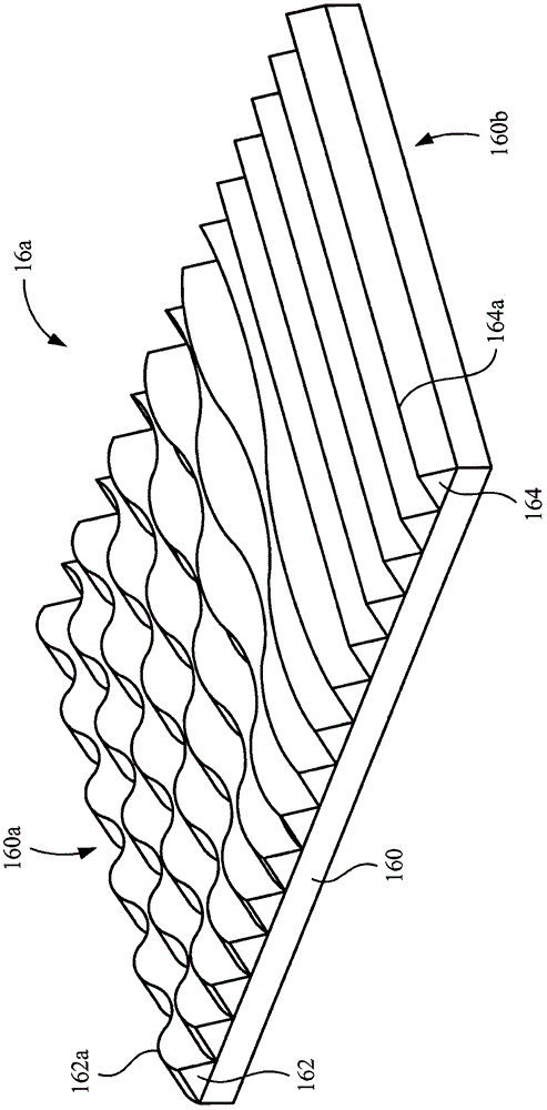
[0071] An embodiment of the invention is a backlight module. More specifically, the purpose of cost reduction is achieved mainly by adopting the optical film of the present invention which can simultaneously have the functions of diffusion and light collection, thereby saving the conventional method of adding an additional diffusion sheet. In other words, the backlight module proposed by the present...


PUM


Abstract

The present invention relates to an optical diaphragm and a backlight module using the same, wherein the optical diaphragm comprises a substrate and a plurality of first prism structures, the substrate is provided with opposite first and second sides, the first prism structures are arranged on the substrate towards to second side from the first side, each prism structure is provided with a bent wave crest, the bent wave crest has a fluctuation degree, and the fluctuation degree of the first prism structure is gradually reduced from the first side to the second side. The optical diaphragm can enable the center brightness of the whole backlight module to be kept at an original level without influencing the luminosity, and can generate an remarkable nebulization effect on the hot point phenomenon generated by an LED. The backlight module can avoid the problem of scrapping between the optical diaphragms and also can reduce the assembling time of the optical diaphragms and the whole thickness of the backlight module with no need of using a diffusing film.

Description

technical field [0001] The invention relates to an optical film, in particular to an optical film applied to a backlight module. Background technique [0002] The backlight module is one of the key components of the liquid crystal display. Since the liquid crystal panel itself does not have the ability to emit light, the function of the backlight module is to supply sufficient brightness and uniformly distributed light source so that the liquid crystal display can display images normally. At present, liquid crystal displays have been widely used in monitors, notebook computers, digital cameras, projectors and other electronic products with growth potential, thus driving the demand for backlight modules and related components to continue to grow. Generally speaking, the backlight module of a liquid crystal display for displaying images usually includes a diffuser, a brightness enhancement film (BEF), an upper diffuser, and a light source. At present, most of the trends of l...

Claims


Application Information

Patent Timeline
Patent Type & Authority Patents(China)
IPC IPC(8): G02F1/13357F21V5/02F21S8/00
CPCG02B5/0231G02B5/045G02B6/0053G02F1/133615
Inventor 林义文郗任远
Owner AU OPTRONICS CORP
Why Eureka
Try Eureka