Spliced rear panel structure for display device

A display device, splicing technology, applied in optics, instruments, nonlinear optics, etc., can solve the problems of insufficient backplane structural strength and outer frame structural strength, difficulty in meeting backplane requirements, and increase in secondary processing costs, etc. Material cost and mold cost, low cost, good strength effect

Active Publication Date: 2012-02-29
TCL CHINA STAR OPTOELECTRONICS TECH CO LTD
View PDF5 Cites 18 Cited by
  • Summary
  • Abstract
  • Description
  • Claims
  • Application Information

AI Technical Summary

Problems solved by technology

However, the back panel structure adopted in the above-mentioned patent uses many installation strips, and the connection and installation are cumbersome, and it still need

Method used


Image

  • Spliced rear panel structure for display device
  • Spliced rear panel structure for display device
  • Spliced rear panel structure for display device

Examples


Embodiment Construction

[0025] In order to further illustrate the technical means adopted by the present invention and its effects, the following describes in detail in conjunction with preferred embodiments of the present invention and accompanying drawings.

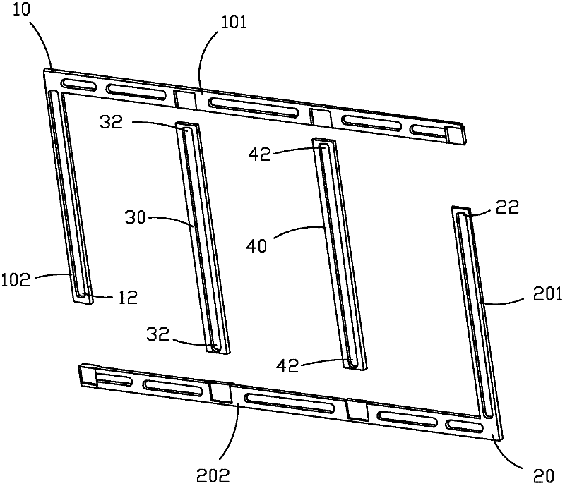
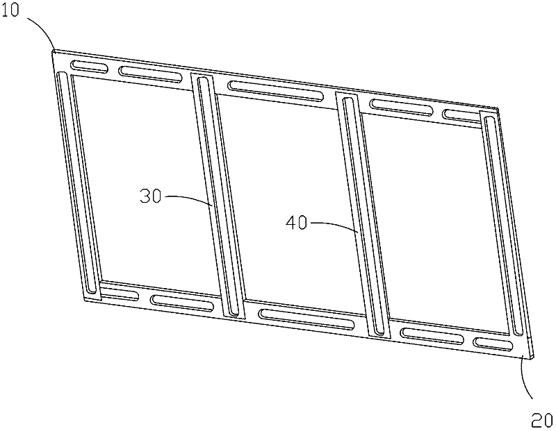
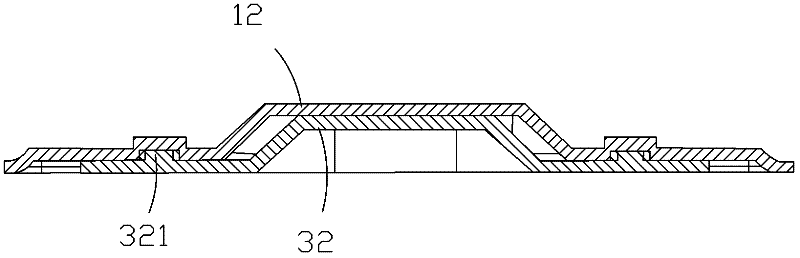
[0026] Such as Figure 1-3 As shown, the present invention provides a spliced ​​back panel structure of a display device, which includes: a first mounting part 10 and a second mounting part 20 which are L-shaped respectively, and a third mounting part 30 and a second mounting part which are in-line respectively. Four mounting parts 40, the two ends of the first mounting part 10 are respectively connected with the two ends of the second mounting part 20 to form a closed outer frame, the third mounting part 30 is placed in the outer frame and the two ends are respectively connected to the first mounting part The component 10 is connected with the second mounting component 20 , the fourth mounting component 40 is placed in the outer frame and its...


PUM


Abstract

The invention provides a spliced rear panel structure for a display device. The spliced rear panel structure comprises an L-shaped first assembling piece, an L-shaped second assembling piece, a linear third assembling piece, and a linear fourth assembling piece, wherein both ends of the first assembling piece are connected with both ends of the second assembling piece to form a closed outer frame; the third assembling piece is arranged in the outer frame, and both ends of the third assembling piece are connected with the first assembling piece and the second assembling piece; and the fourth assembling piece is arranged in the outer frame, and both ends of the fourth assembling piece are connected with the first assembling piece and the second assembling piece to form a hollowed rear panel. The spliced rear panel structure has the outer frame with high structure strength, and is low in cost and easy to manufacture; the assembling pieces can be spliced to form rear panels in different sizes after being segmented, and a production mold for the rear panels can be shared, so that the material cost and the mold cost are lowered.

Description

technical field [0001] The invention relates to a spliced ​​backplane structure of a display device, in particular to a spliced ​​backplane structure applied to a backlight module of a TFT-LCD display device. Background technique [0002] The liquid crystal display device is referred to as LCD (Liquid Crystal Display). Its working principle is to place liquid crystal molecules between two parallel glasses. , to refract light to produce a picture. Since the liquid crystal display device has many advantages such as thin body, power saving, and no radiation, it has been widely used. The backlight module is an important part of the liquid crystal display device. The existing backlight module generally includes an optical film, a light guide plate, a backlight unit, and a backplane. In order to meet the needs of large-size liquid crystal display devices, the existing backplane generally An integral backplane is generally integrally formed by metal stamping or plastic injection....

Claims


Application Information

Patent Timeline
IPC IPC(8): G02F1/13H05K5/02
CPCG02F1/133308G02F1/133608G02F1/133314G02F1/133328G02F1/133628
Inventor 郭仪正萧宇均黄冲程加河阙成文李全杨流洋
Owner TCL CHINA STAR OPTOELECTRONICS TECH CO LTD
Why Eureka
Try Eureka