
Stabilized DC power source device

一种稳定电源、直流输入电压的技术,应用在电路装置、交流网络电路、输出功率的转换装置等方向,达到电压转换效率高的效果

Inactive Publication Date: 2012-03-07
ONAMBA CO LTD
View PDF8 Cites 2 Cited by
  • Summary
  • Abstract
  • Description
  • Claims
  • Application Information

AI Technical Summary

Problems solved by technology

However, in this configuration, problems similar to those of Patent Document 1 still exist

Method used


Image

  • Stabilized DC power source device
  • Stabilized DC power source device
  • Stabilized DC power source device

Examples


no. 1 example

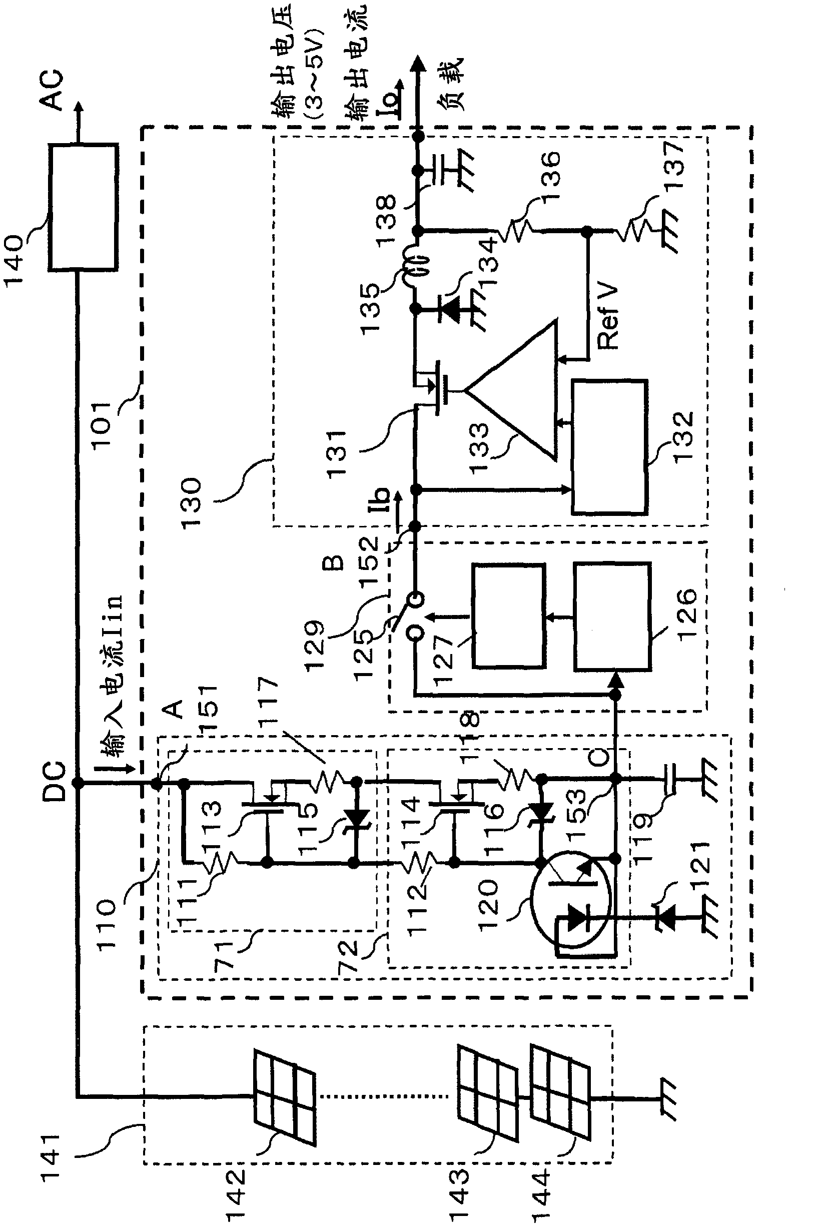
[0046] figure 1 It is a configuration diagram of the first embodiment of the DC stabilized power supply device of the present invention. exist figure 1 In which, the solar cells 141 connected in series with each other by photovoltaic power generation modules 142, 143 and 144 output DC power in response to light intensity from solar radiation, and generally supply DC power to the input of the inverter 140, which makes the The DC power is converted to commercial AC power for use in homes, etc. The DC stabilized power supply device 101 comprises: a first constant voltage power supply circuit 110 responsible for constant current control, which is connected in series and used to reduce voltage; a switch circuit 129 has a voltage detection circuit 126 and a Schmidt (Schmidt) trigger circuit 127 , the Schmitt trigger circuit 127 turns to a closed state when the voltage value is V1 or higher, and turns to an open state when the voltage value is V2 or lower; Power circuit 130.

...

no. 2 example

[0063] Figure 5 It is a configuration diagram of the second embodiment of the DC stabilized power supply device of the present invention. exist Figure 5 , the same reference numerals are used for the figure 1 with Figure 8 are the same as those components in , so their descriptions are omitted.

[0064]The difference between the second embodiment and the first embodiment is that the switch circuit 160 uses the input voltage of the DC stabilized power supply device 102, which is used as the detection input voltage of the voltage detection circuit 161, which is the output voltage of the solar battery 141, and when the When the detection voltage is a voltage value V3 or higher, the switch circuit 160 is allowed to have the function of turning the switching element 163 to a closed state by means of the Schmitt trigger circuit 162, and when the detection voltage becomes a voltage value V4 or When it is lower, the switching element 163 is turned to the off state by the action...


PUM


Abstract

Disclosed is an inexpensive power source device with which a stable power source required for low-voltage measurement equipment is supplied from a high voltage solar battery power source which is subject to severe variations. A stabilized DC power source device which steps down DC input voltage obtained from a solar battery and outputs the stepped-down voltage to a load such as measurement equipment, wherein the stabilized DC power source device comprises: a series-type first constant-voltage power source circuit that performs voltage step-down and is connected to the solar battery and provided with a constant-current control circuit; a switching circuit that is connected to the first constant-voltage power source circuit; a switchable second constant-voltage power source circuit that is connected to the switching circuit; and a voltage detection circuit that detects the output voltage of the first constant-voltage power source circuit. The output voltage of the first constant-voltage power source circuit is detected and, if the detected voltage is greater than or equal to a first determination voltage, the switching circuit is closed and power is supplied to the load from the second constant-voltage power source circuit. If the detected voltage is less than or equal to a second determination voltage, which is lower than the first determination voltage, the switching circuit is opened and the power supplied to the load from the second constant-voltage power source circuit is stopped.

Description

technical field [0001] The present invention relates to a DC stabilized power supply device that lowers the voltage of a power supply from a solar cell whose output power is unstable and supplies necessary stabilized voltage to measuring equipment and the like. Background technique [0002] In recent years, in order to cope with the problem of global warming, power generation systems of solar cells have been rapidly and widely developed. In addition, the efficiency of the power generation system has been enhanced, and its working equipment has been improved to be stable. Therefore, in the case where the scale of the power generation equipment is large, the measurement equipment associated therewith becomes necessary, and performances of saving power and allowing stable operation are also required in order to supply power to the measurement equipment. [0003] So far, in the case where the power supply voltage on the supply side for operating the measuring device and the pow...

Claims


Application Information

Patent Timeline
Patent Type & Authority Applications(China)
IPC IPC(8): G05F1/67
CPCH01L31/02021H02M3/156H02J2300/24H02J3/381Y02E10/56H02M1/0045G05F1/468
Inventor 静谷治宫田幸隆小西康文
Owner ONAMBA CO LTD
Learn More