
Flexible and rapid clamp device

A fixture device, fast technology, applied in the direction of positioning device, clamping, manufacturing tools, etc., can solve the problems of increasing the cost of process equipment and production preparation cycle, deformation of the crankshaft, and lack of auxiliary positioning function, so as to shorten the production preparation cycle , the effect of improved precision

Inactive Publication Date: 2012-03-14
杭州杭机数控机床有限公司
View PDF11 Cites 12 Cited by
  • Summary
  • Abstract
  • Description
  • Claims
  • Application Information

AI Technical Summary

Problems solved by technology

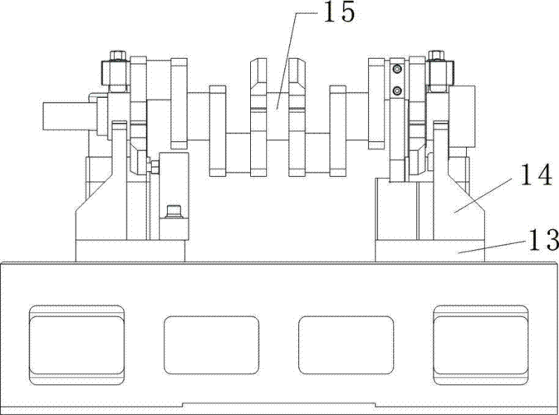
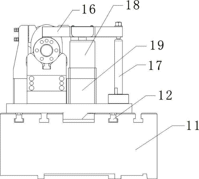
The special fixture of the above structure is positioned at the crankshaft journal through the V-shaped brackets 14 at both ends of the crankshaft. Therefore, the positioning stability during the clamping process is poor. Positioning phenomenon, if the clamping force is too large, it will easily cause the deformation of the crankshaft, if the clamping force is too small, it will not be able to assist positioning
The fixture needs to be clamped twice, and the working efficiency of the fixture is low
In addition, the fixture cannot be used for crankshaft processing of different specifications. When changing products, the corresponding fixture needs to be replaced, which increases the cost of process equipment and the production preparation cycle

Method used


Image

  • Flexible and rapid clamp device
  • Flexible and rapid clamp device
  • Flexible and rapid clamp device

Examples


Embodiment Construction

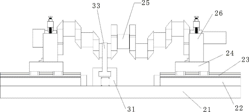
[0014] The present invention will be described in detail below in conjunction with accompanying drawing: image 3 , 4 , 5, the present invention mainly includes a base plate 21, a guide rail support 22 is respectively arranged on the left and right sides of the base plate 21, and a carriage 24 is respectively installed by a guide rail 23 on it. The V-shaped block 26 of neck, on the slewing bearing journal of crankshaft, clamp with rotary oil cylinder pressing plate mechanism, the crank throw side in the middle of crankshaft 25 is provided with an automatic centering mechanism and clamps to the crank throw both sides to realize auxiliary positioning.

[0015] Figure 4 The rotary oil cylinder pressing plate mechanism shown includes an upper pressing plate 27 pressed against the crankshaft on the slewing bearing journal, one end of the pressing plate 27 is fixed to the oil cylinder base 29 through an adjustable screw 28, and the oil cylinder base 29 is installed An oil cyl...


PUM


Abstract

The invention relates to a flexible and rapid clamp device which comprises a baseplate, wherein guide rail supports are respectively arranged at the left and the right of the baseplate, carriages are respectively mounted on the guide rail supports through guide rails, a V-shaped block for positioning a revolving support shaft neck of a crankshaft is respectively arranged on each carriage, the revolving support shaft neck of the crankshaft is clamped through a revolving oil cylinder pressure plate mechanism, an automatic centering mechanism is arranged on the side edge of a crank at the middle of the crankshaft and the two sides of the crank are clamped for realizing auxiliary positioning; the revolving oil cylinder pressure plate mechanism comprises a pressure plate which is compressed on the revolving support shaft neck of the crankshaft, one end part of the pressure plate is fixed on an oil cylinder base through an adjustable screw rod, and an oil cylinder connected with the middle part of the pressure plate is mounted on the oil cylinder base; and the automatic centering mechanism comprises a middle guide rail mounted on the baseplate, and a middle support for performing auxiliary positioning on one pair of the side edges of the crank is connected on the middle guide rail through a crank oil cylinder. The flexible and rapid clamp device has the characteristics of being simple in structure, being convenient to use and having good stability in positing during the clamping process, high positioning precision, high working efficiency and the like.

Description

technical field [0001] The invention relates to a special clamp for processing the structure of the end of a crankshaft, in particular to a flexible quick clamp device for processing the structure of the end of a crankshaft. Background technique [0002] figure 1 , 2 Shown is a special fixture for crankshaft end structure processing developed and applied by a company in Taiwan. It includes a workbench 11, on which two base plates 13 are installed on the work table 11 through slide rails 12, and each base plate 13 is equipped with a V-shaped support 14, and the crank journal of crankshaft 15 is positioned with this V-shaped support 14, clamps with an end of a swing pressing plate 16 above described crank axle journal; The other end of described swing pressing plate 16 is fixed on The supporting rods 17 on the bottom plate 13 are connected, and the middle of the swing platen 16 is connected with an oil cylinder 18. The oil cylinder 18 is installed on an oil cylinder base...

Claims


Application Information

Patent Timeline
Patent Type & Authority Applications(China)
IPC IPC(8): B23Q3/06
Inventor 常新山秦宝荣杜建军石俊瑜胡颖斌
Owner 杭州杭机数控机床有限公司
Learn More